The air compressor is located on the engine and operates only when the engine is running. Clean, filtered, turbocharged pressurized air from the intake manifold is force-fed into the air compressor. The compressor maintains the air system whenever the system’s pressure falls below preset parameters. When the maximum pressure is reached, the compressor output is diverted. An air governor is used to maintain the air pressure from 85 to 125psi.
Air pressure build-up test. Continue to let the air pressure build; it should not take more than four minutes for the air pressure to go from discharged (5-20 psi) to between 120 and 130 psi.
Governor cut-in/cut-out test. When air pressure gets between 120-130 psi, the governor should cut out. The dash gauge needle stops moving. When the needle stops, pump the brake pedal to reduce the air pressure to 80 psi, release the brake pedal, the compressor starts pumping air (cutting in)! watch for needle movement. The air governor causes the air compressor to cut in between (85-90 psi).
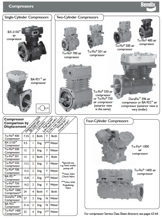
Usually driven by the vehicle engine, the air compressor builds the air pressure for the air brake system. The air compressor is typically cooled by the engine coolant system and lubricated by the engine oil supply. (Certain models have self-lubricated and/or air-cooled versions available.) Note: Air compressor shafts can rotate in either direction.
The vehicle’s compressor draws in filtered air, either at atmospheric pressure from the outside (or already at increased pressure, from the engine turbocharger where permitted) and compresses it.
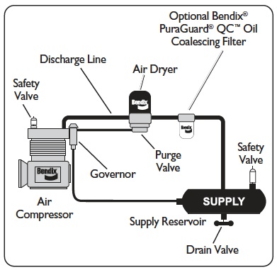
The brake system needs a supply of compressed air between a preset maximum and a minimum. The governor (along with a synchro valve for the Bendix® DuraFlo™ 596 air compressor) monitors the air pressure in the supply reservoir and controls when the compressor needs to pump air into the air system (also known as the “air build cycle” – the compressor is “running loaded”) and when the compressor should simply turn over without building pressure (“running unloaded”). When the air pressure becomes greater than that of the preset “cut-out”, the governor controls the unloader mechanism of the compressor to stop the compressor from building air and also causes the air dryer to purge. As the service reservoir air pressure drops to the “cut-in” setting of the governor, the governor returns the compressor back to building air and the air dryer to air drying mode.
As the atmospheric air is compressed, all the water vapor originally in the air is carried along into the air system, as well as a small amount of the compressor lubricating oil as vapor.
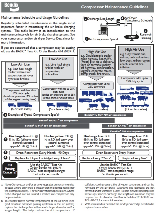
The duty cycle is the ratio of time the compressor spends building air to the total engine running time. Air compressors are designed to build air (run “loaded”) up to 25% of the time. Higher duty cycles cause conditions (such as higher compressor head temperatures) that affect air brake charging system performance. These conditions may require additional maintenance and lead to a higher amount of oil vapor droplets being passed along into the air brake system. Factors that add to the duty cycle are air suspension, additional air accessories, use of an undersized compressor, frequent stops, excessive leakage from fittings, connections, lines, chambers or valves, etc. See page 9 for compressor maintenance and usage guidelines. Use the BASIC™ test (p/n 5013711) where the amount of oil present in the air brake system is suspected to be above normal.
The discharge line allows the air, water vapor and oil vapor mixture to cool between the compressor and air dryer. The typical size of a vehicle’s discharge line, (see table on page 9) assumes a compressor with a normal (less than 25%) duty cycle, operating in a temperate climate. See Bendix and/or vehicle or air dryer manufacturer guidelines as needed.
When the temperature of the compressed air that enters the air dryer is within the normal range, the air dryer can remove most of the charging system oil. If the temperature of the compressed air is above the normal range, oil as oil-vapor is able to pass through the air dryer and into the air system. Air dryer inlet temperatures play a key role in air system cleanliness and air dryer performance. Larger diameter discharge lines and/or longer discharge line lengths can help reduce the temperature.
The discharge line must maintain a constant slope down from the compressor to the air dryer inlet fitting to avoid low points where ice may form and block the flow. If instead, ice blockages occur at the air dryer inlet, insulation may be added here, or if the inlet fitting is a typical 90-degree fitting, it may be changed to a straight or 45-degree fitting. For more information on how to help prevent discharge line freeze-ups, see Bendix Bulletins TCH-08-21 and TCH-08-22. Shorter discharge line lengths or insulation may be required in cold climates.
The air dryer contains a filter that collects oil droplets and a desiccant bed that removes almost all of the remaining water vapor. The compressed air is then passed to the air brake service (supply) reservoir. The oil droplets and the water collected is automatically purged at the dryer when the governor reaches its “cutout” setting.
For vehicles with accessories that are sensitive to small amounts of oil, we recommend installation, downstream of the air dryer, of a Bendix® PuraGuard® QC™ oil coalescing filter to minimize the amount of oil present.