| Operating VDC Limits | 4.75 VDC min/18VDC max |
| Operating Temperature | -20 to 85º C |
| Physical Attributes | 3.25″ wide, 3.25″ high, .5″ deep |
| Weight: 0.45 lbs. | |
| Aluminum case, epoxy sealed (black) | |
| High/Low Pot Adjustments | 10-15VDC |
| Standby Current Draw | 12 Milli Amps |
| Operating Current Draw | 160 Milli Amps |
| Run Output | 5 Amps max continuous sourcing(+bat) output |
Monitors the state of charge of a battery bank to activate the charging system to ensure full recharging. Can trigger any type of charging system including line chargers and engine-generators. Operates on both 12 and 24V battery bank systems.
The high and low setpoints to begin and end the charging cycle are adjustable within a range of values.
ADJUSTMENTS AND SETUP PROCEDURES
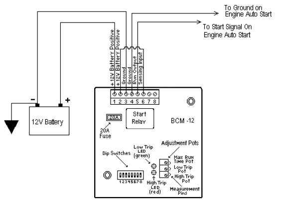
“Potentiometer” is abbreviated as ì“potî” throughout. To increase a pot’s setting, turn it clockwise; to decrease it, counter-clockwise. These Pots are 25 turns nominal, therefore turn pots fully 25 turns to ensure that you are at either the minimum or maximum setting. The rear of the BCM unit contains three adjustable pots, and an eight-position DIP switch, only 3 switches are implemented on this unit.
The steps for calibration of the BCM unit to a specific system is as follows:
1. Calibration of LOW trip setpoint.
2. Calibration of HIGH trip setpoint.
3. Adjustment of Maximum run-time setting.
4. Adjustment of Delay On timer setting.
Foretravel Bulletin Number: B003100.002
When installing a Battery Charge Monitor (BCM-12) for the operation of the auto start feature on generators, the parameters of the potentiometers must be adjusted to the following:
| Max run timer | 2.34 vdc | 4 hours |
| Low set point | 2.2 vdc | 12.2 vdc |
| High setpoint | 4.0 vdc | 14.0 vdc |
Foretravel Bulletin Number: B003100.003
Upon installation of the updated Dyna-Gen® module, a distinction must be made of the type engine used in the generator.
The updated module has a preheat default setting of 8 seconds. This is accomplished by a small black jumper that makes a loop out of the potting on the module board. By leaving this wire intact, the unit will automatically set preheat to 8 seconds. Clipping this loop will double the time to 16 seconds.
Settings are as follows:
1) Isuzu engines are to be left at the default setting of 8 seconds.
2) Kubota engines are to be set at 16 seconds by clipping the loop.
LOW SETPOINT CALIBRATION
The low set point range spans from 10 – 15VDC. This setpoint is adjustable via an onboard Pot. There is a green LED adjacent to the Pot (LOW), which illuminates when the sense input voltage has gone below the low set point. There is also a jumper adjacent to the LOW pot, which allows for pot calibration.
The simplest and most precise method for calibration is as follows.
1. Connect battery positive (10 – 15 VDC) to BCM terminal #1 or #2, and connect battery negative to BCM terminal #3 or #4.
2. Measure the voltage on the jumper adjacent to the LOW Potentiometer. The Low setpoint will be the voltage measured at the jumper pin +10. [LOW SETPOINT= V measured +10 VDC] i.e. If a LOW setpoint of 12.1VDC is required, you must adjust the low potentiometer until the voltage at the LOW POT reads 2.1VDC.
HIGH SETPOINT CALIBRATION
The HIGH setpoint range spans from 10 – 15VDC. This setpoint is adjustable via an onboard Pot. There is a red LED adjacent to the Pot (HIGH), which illuminates when the sense input voltage has gone above the HIGH set point. There is also a jumper adjacent to the HIGH pot, which allows for pot calibration.
The simplest and most precise method for calibration is as follows.
1.
Connect battery positive (10 – 15 VDC) to BCM terminal #1 or #2, and connect
battery
negative to BCM terminal #3 or #4.
2. Measure the voltage on the jumper adjacent to the HIGH Potentiometer. The HIGH setpoint will be the voltage measured at the jumper pin +10.
[HIGH SETPOINT= V measured +10 VDC] i.e. If a HIGH setpoint of 14.2VDC is required, you must adjust the HIGH potentiometer until the voltage at the HIGH POT reads 4.2VDC.
MAXIMUM RUN TIME CALIBRATION
The Maximum Run time setting is adjustable from 0 – 512 minutes (0 – 8.5 hrs). This setting adjusts the maximum ON time for the Run output. i.e. if the HIGH setpoint has not been reached prior to the maximum run time, the Run output turns OFF, and the BCM waits for yet another LOW voltage condition.
Calibration of the maximum run time is as follows:
1. Connect battery positive (10 – 15 VDC) to BCM terminal #1 or #2, and connect battery negative to BCM terminal #3 or #4.
2.
Measure the voltage on the jumper adjacent to the MAX. RUN TIME Potentiometer.
The MAX RUN TIME set point will be as follows:
[MAX RUN TIME = (V measured * 512)/5)]
i.e. If a MAX RUN TIME of 5 minutes is required then you must adjust the MAX
RUN
TIME potentiometer until the voltage at the MAX RUN TIME POT reads 0.0488 VDC.
V meas. = (MAX RUN TIME * 5)/512 = (5*5)/512
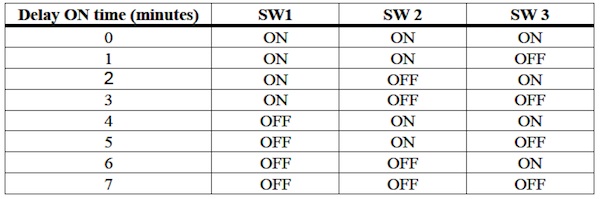
DELAY ON TIME CALIBRATION
The Delay ON timer provides an adjustable delay for activation of the Run output. i.e. if the sense input voltage drops below the LOW set point, the BCM delays the activation of the Run relay for the delay ON period.
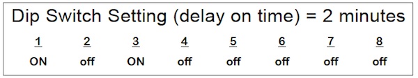
The Delay ON timer function is configurable from DIP switches 1, 2 & 3. The Delay ON timer has eight possible settings as follows: