1. CENTROID’S PROGRAMMABLE FUEL AND WATER SENDERS
Centroid’s new microcontroller-based senders can be distinguished from our older analog style by a “P” in the part number: ie CGFP or CGWP. Senders with aluminum tubing are for oil, diesel, or gasoline of up to 10% ethanol; and senders with PVC tubing are for potable water. We don’t make units for non-potable water, which leaves conductive deposits on the sense wire.
2. HOW THE SENDERS MEASURE LIQUID LEVEL
Centroid’s senders work by measuring capacitance. This means no moving parts are required. Electronics in the head convert this measured capacitance to the programmed output of ohms or volts. In fuel senders, capacitance is measured between the inner sensing tube and the grounded outer tube and requires the fluid to be non-conductive. In water senders, capacitance is measured between the inner insulated sense wire and the water, which is grounded by the outer wire.
3. SHORTENING SENDERS (if required)
A fuel sender’s outer tube can be shortened using a tubing cutter, and the inner tube snipped. Unless the sender was ordered as bendable, bending the tubing risks shorting the inner to the outer tube, which causes a false Empty reading. A sender ordered as bendable can be safely bent above the black bend line on the tubing because it is insulated internally above that line.
Shortening a water sender requires the following steps:
1) Unwind the outer ground wire
2) Pull the PVC tube from its friction fit on the head to expose the white sense wire
3) Use a heat gun to soften and pull off the black sealing piece at the end of the white wire
4) Shorten both wires and the tube
5) Put the black sealing piece back on tile shortened white wire and heat it to get a good seal again (important!)
6) Put on the outer tube and rewrap the outer ground wire.
4. CONNECTIONS
NEG connects this to DC ground. NOTE: our senders work with negative-ground systems only. SEND connect this to the Send input of your gauge or display.
NOTE: this is an electronic output that will confuse your ohmmeter if you try to take a resistance reading. Instead, we troubleshoot by voltages, while connected to the gauge.
POS (most senders): Most Centroid senders have an ignition-voltage pas terminal to run their electronics. A fused voltage between 11-28vdc should be wired to the POS connection. The voltage should turn off when the system is turned off, both for safety and to avoid running down the battery. For a number of brands of 240/33 ohm gauge (not all), we can make a special sender that doesn’t have this pas connection. These senders run their electronics from the voltage on the Send connection. ALARM (if ordered): The ALARM output switches to the ground when the sender is in a factory-programmed alarm state, meaning a low or high level.
A DC load that requires 0.3A or less can be connected to this output, with the far side of the load connected to battery voltage. Typically the load is an alarm light. During an alarm, If the ALARM output is momentarily shorted to NEG by a pushbutton switch, the alarm will turn off until a new alarm condition occurs. This is convenient for audible alarms.
5. CALIBRATION
A. OUTPUT RANGE AND ALARM LEVELS ARE NOT CHANGEABLE BY THE CUSTOMER
The output range (e9 240/33 ohms) and alarm levels (if ordered) are set at the factory per the customer’s order. They cannot be changed by the end-user. They can be changed back at the factory if needed, however.
B. EMPTY LEVEL ON SENDERS WITH THREE OR FOUR SCREW TERMINALS
The Empty level will already be calibrated to be the bottom of the sender if you use the sender at its factory length. If you’ve shortened the sender, the Empty should be recalibrated with the following steps. The timing is important. 1) have the sender out of the tank and wired normally, but power off; 2) have SEND temporarily jumpered to NEG; 3) turn the power on, but remove the SEND/NEG jumper after TWO SECONDS (1000-1, 1000-2). he needle will then do some bouncing and finish on Empty If it finishes somewhere other than E or lower, there is a wiring problem or mismatched output range. Please email/fax for help
C. FULL LEVEL ON SENDERS WITH THREE OR FOUR SCREW TERMINALS
For fuel senders with “-FD” in the part number, the Full level is automatically detected by a special sensor each time you fill the tank. So the Full level does not have to be set manually. If you’d prefer to set it manually, follow the underlined steps in the previous paragraph, using the appropriate fuel rather than water. The automatic mode helps the sender respond correctly to gasoline with ethanol or biodiesel, however.
Full will be calibrated at the factory a couple of inches below the sender’s head. If you’ve shortened the sender, or prefer a different Full height. the Full can be recalibrated with the following steps
1) Have sender in full tank (or tube) of the appropriate liquid, and wired normally, but power off
2) Have to SEND temporarily jumpered to NEG
3) Turn the power on, but remove the SEND/NEG jumper after FIVE SECONDS (1000-1,1000-2,1000-3,1000-4,1000-5)
The needle will then do some bouncing and finish on Full. If it finishes somewhere other than F or higher, there is a wiring problem or mismatched output range.
D. SENDERS WITH TWO SCREW TERMINALS, AND SENDERS WITH WIRES OR CONNECTORS
A rare-earth magnet (provided with the sender, or use Radio Shack 64-1895) is used to set Empty and/or Full on senders with two terminals, or with wires or connectors. The word MAG with an arrow should be found on the label. Instead of shorting terminals in steps 58 and 5C, place the magnet vertically on the surface of the epoxy, above the MAG arrow, for the seconds listed. That will internally cause the desired short.
6. HELP
We provide free tech support, but by email or fax only. You’ll always get an answer the same working day, and usually within an hour. 12-11-2008
On the Oshkosh chassis, the fuel tank is located between the chassis rails and seems like it is 10′ long. The fuel fill pipe is about 4′ long and comes down at an angle from the opening beneath the driver’s window and then enters the tank halfway up. I never have understood how I am able to get it full (sort of, as I give up after a few burps).
Based on the Oshkosh drawing of the fuel tank the sender is located on the top of the tank and would require removing the tank to get at it unless Foretravel put in an access plate on the coach floor. John Cooper 91 GV 36′ Oshkosh chassis
Foretravel did not make an opening in the floor of the coach. The tank will have to be dropped. The Oshkosh sender is a float type sender, with ohms resistance depending on the gauge that was installed. That is the correct procedure. James Triana
When I purchased my 95 U320 in April, the fuel gauge was absolutely useless. I removed the 3 screws holding the connectors on the sender, cleaned all contact surfaces with a plastic scrubber and reinstalled. After adjustment, the fuel gauge seems to be quite accurate. I only have a few fill-ups to judge from. I wonder if the erratic behavior was caused by dirty contacts, rather than bad potentiometers. Wyatt Sabourin 1996 U320 40′
I had my facts twisted on a couple of items:
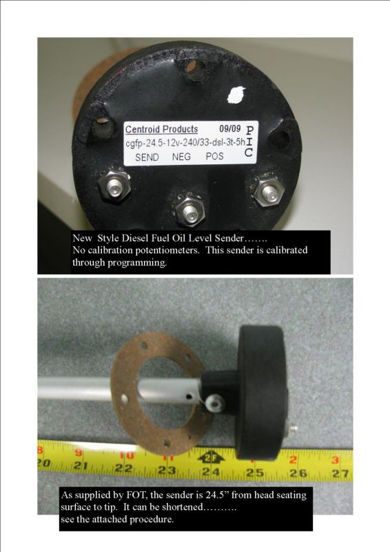
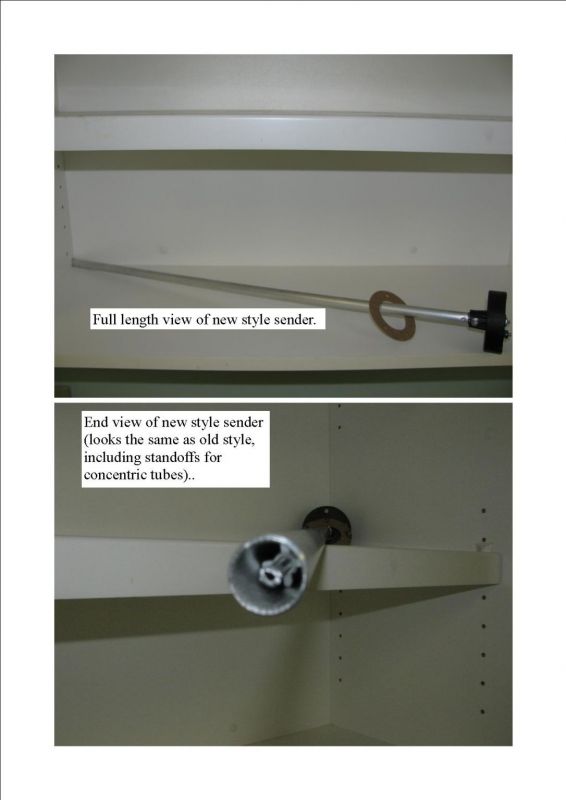
* The two sensor heads don’t look identical because the new sensor head does not have the “empty” and “full” calibration potentiometers……….it is strictly digital and programmable, as you will see from the pictures and procedure.
* It’s not an auto-zero (empty) but actually an auto (full), start point, once the sensor has been programmed to a known FULL tank. That should go a long way toward resolving the “flaky readings” that we often see during the top half of fuel tank usage.
I’ve had both problems. The first time, I took the wiring off both the sender and the dash gauge, cleaned, used dielectric grease and that fixed the problem for several years. The second time, repeating all of the above had no effect and tank level would read full one evening and 1/2 full the next morning. Just plain erratic behavior that would “come and go”.
Then I calibrated the (old style) analog sender IAW the Centroid instructions. It would only stay reliable for short periods of time. FOT recommended changing the sender, which totally cured the problem for several years after.
Then, last fall the second (still the old-style analog) sender started acting up, again. Cleaned connections at both ends again. No improvement.
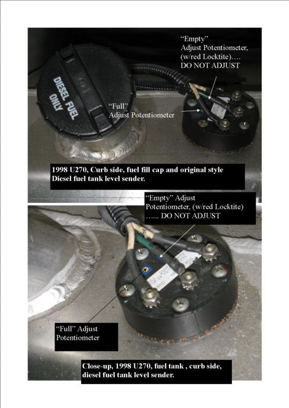
Once again, I recalibrated my old sensor and this time I put a dab of red Locktite on the Potentiometer adjustment screw head. It seems to still be holding 10 months later, but I have had a couple of erratic readings. Once, it read 1/2 full for several hundred miles, starting on a nearly full tank. Then, at about 1/2 tank, it started working again. Carrying a spare sometimes has that GREAT effect!
However, I don’t actually know if the new style is better than the old, as they (FOT) claim. But, being digital and programmable seems like the right direction for improved stability.
The Centroid sender potentiometers just might be the weak point in the old sender design. As many of us have found out, when they start to bother, they often won’t stay stable, particularly after readjustment.
Be aware that there is a new direct plug-in replacement Centroid sender that is digital and programmable, that should resolve the instability. I bought mine directly from FOT last winter.