DESCRIPTION
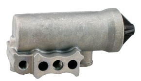
The D-2TM governor, operating in conjunction with the unloading mechanism, automatically controls the air pressure in the air brake or air supply system between a maximum (cut- out) pressure and a minimum (cut-in) pressure. The compressor runs continually while the engine runs, but the actual compression of air is controlled by the governor actuating the compressor unloading mechanism which stops or starts the compression of air when the maximum or minimum reservoir pressures are reached. D-2TM governors are provided with mounting holes that allow direct mounting to the compressor or remote mounting. Porting consists of three reservoir ports (1/8 inch P.T.), three unloader ports (1/8 inch P.T.) and one exhaust port (1/8 inch P.T.).
OPERATION
Reservoir air pressure enters the D-2TM governor at one of its reservoir ports and acts on the piston and inlet/exhaust valve. As the air pressure builds up, the piston and valve move together against the resistance of the pressure setting spring. When the reservoir air pressure reaches the cut-out setting of the governor, the exhaust stem seats on the inlet/exhaust valve, closing the exhaust passage and then opens the inlet passage. Reservoir air pressure then flows around the inlet valve, through the passage in the piston and out the unloader port to the compressor unloading mechanism. Air also flows around the piston which is slightly larger at the upper end. The added force resulting from this larger area assures a positive action and fully opens the inlet valve. As the system reservoir air pressure drops to the cut-in setting of the governor, the force exerted by the air pressure on the piston will be reduced so that the pressure setting spring will move the piston down. The inlet valve will close and the exhaust will open. With the exhaust open, the air in the unloader line will escape back through the piston, through the exhaust stem, and out the exhaust port.
PREVENTIVE MAINTENANCE
Important: Review the Bendix Warranty Policy before performing any intrusive maintenance procedures. A warranty may be voided if intrusive maintenance is performed during the warranty period. No two vehicles operate under identical conditions, as a result, maintenance intervals may vary. Experience is a valuable guide in determining the best maintenance interval for air brake system components. At a minimum, the D-2TM governor should be inspected every 6 months or 1500 operating hours, whichever comes first, for proper operation. Should the D-2TM governor not meet the elements of the operational tests noted in this document, further investigation and service of the governor may be required.
SERVICE TESTS
OPERATING TESTS
Start the vehicle engine and build up air pressure in the air brake system and check the pressure registered by a dash or test gauge at the time the governor cuts-out, stopping the compression of air by the compressor. The cut-out pressure should be in accordance with the pressure setting of the piece number being used. (Common cut-out pressures are between 105-125 psi.) With the engine still running, make a series of brake applications to reduce the air pressure and observe at what pressure the governor cuts-in the compressor. As in the case of the cut-out pressure, the cut- in pressure should be in accordance with the pressure setting of the piece number being used. (Common cutting pressures are between 90-105 psi.)
Never condemn or adjust the governor pressure settings unless they are checked with an accurate test gauge or a dash gauge that is registering accurately. If the pressure settings of the D-2TM governor are inaccurate or it is necessary that they are changed, the adjustment procedure follows.
Note: If the governor cover is marked nonadjustable and the adjusting stem has been sheared off, this is a non-serviceable governor and must be replaced with a new or remanufactured unit.
A. Remove the top cover from the governor.
B. Loosen the adjusting screw locknut.
C. To raise the pressure settings, turn the adjusting screw counter-clockwise.
To lower the pressure settings, turn the adjusting screw clockwise.
Note: Be careful not to over adjust. Each 1/4 turn of the adjusting screw raises or lowers the pressure setting approximately 4 psi.
D. When the proper adjustment is obtained, tighten the adjusting screw locknut and replace the cover. (Note: The pressure range between cut-in and cut-out is not adjustable.)
LEAKAGE TEST
Leakage tests on the D-2TM governor should be made in both cut-in and cut-out positions.
CUT-IN POSITION
Apply soap solution around the cover and to the exhaust port. Slight bubble leakage permitted. Excessive leakage indicates a faulty inlet valve or lower piston o-ring.
CUT-OUT POSITION
Apply soap solution around the cover and to the exhaust port. Slight bubble leakage permitted. Excessive leakage indicates a faulty exhaust valve seat, exhaust stem o-ring, or o-ring at the top of the piston. If the governor does not function as described or leakage is excessive, it is recommended that it be replaced with a new or remanufactured unit, or repaired with genuine Bendix parts available at authorized Bendix parts outlets.
WARNING! PLEASE READ AND FOLLOW THESE INSTRUCTIONS TO AVOID PERSONAL INJURY OR DEATH:
When working on or around a vehicle, the following general precautions should be observed at all times.
1. Park the vehicle on a level surface, apply the parking brakes, and always block the wheels. Always wear safety glasses.
2. Stop the engine and remove the ignition key when working under or around the vehicle. When working in the engine compartment, the engine should be shut off and the ignition key should be removed. Where circumstances require that the engine be in operation,
EXTREME CAUTION should be used to prevent personal injury resulting from contact with moving, rotating, leaking, heated or electrically charged components.
3. Do not attempt to install, remove, disassemble or assemble a component until you have read and thoroughly understand the recommended procedures. Use only the proper tools and observe all precautions pertaining to the use of those tools.
4. If the work is being performed on the vehicle’s air brake system, or any auxiliary pressurized air systems, make certain to drain the air pressure from all reservoirs before beginning ANY work on the vehicle. If the vehicle is equipped with an AD-ISTM air dryer system or a dryer reservoir module, be sure to drain the purge reservoir.
5. Following the vehicle manufacturer’s recommended procedures, deactivate the electrical system in a manner that safely removes all electrical power from the vehicle.
6. Never exceed manufacturer’ s recommended pressures.
7. Never connect or disconnect a hose or line containing pressure; it may whip. Never remove a component or plug unless you are certain all system pressure has been depleted.
8. Use only genuine Bendix® replacement parts, components, and kits. Replacement hardware, tubing, hose, fittings, etc. must be of equivalent size, type and strength as original equipment and be designed specifically for such applications and systems.
9. Components with stripped threads or damaged parts should be replaced rather than repaired. Do not attempt repairs requiring machining or welding unless specifically stated and approved by the vehicle and component manufacturer.
10. Prior to returning the vehicle to service, make certain all components and systems are restored to their proper operating condition.
REMOVING AND INSTALLING REMOVING
1. Block and hold vehicle by means other than air brakes.
2. Drain air brake system.
3. If the governor is compressor-mounted type, disconnect reservoir air line. If the governor is remote-mounted, disconnect both the unloader and reservoir air lines.
4. Remove governor mounting bolts, then governor. Caution: Prior to disassembly, it is required to have the proper maintenance kit available to replace parts to be discarded during disassembly.
DISASSEMBLY
1. Clean the governor’s exterior of dirt and grease.
2. If the governor cover is marked nonadjustable and the adjusting screw has been sheared off, this is a non-serviceable governor and must be replaced with a new or remanufactured unit.
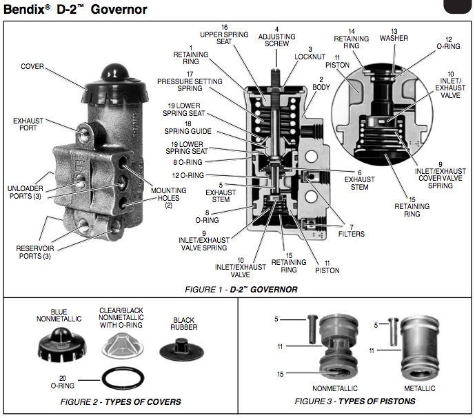
3. If the governor has a blue nonmetallic cover, (refer to Figure 2) hold governor with one hand, with the other hand grip cover from the top and pull up with thumb until cover disengages from the governor’s body. If the top cover on the governor is made of rubber or clear nonmetallic material unscrew cover until it releases from the adjusting screw (4) of the governor. Remove o-ring (20, Figure 2) if present. Note: O-ring (20) is used on Hi-Temp and waterproof governors only.
4. With a pair of retaining ring pliers, remove the spring assembly retaining ring (1) and save.
5. Pull the adjusting screw (4) and spring assembly out of the governor’s body (2). Note: Disassembly of the spring assembly normally is not required. (Reuse and do not wash the assembly because lubrication may be removed.) If Disassembly of the spring assembly is necessary, the following instructions apply; otherwise, proceed to Step 6. Remove the locknut (3), then the hex-shaped upper spring seat (16) from the adjusting screw (4). Remove the pressure setting spring (17), lower spring seat (19), spring guide (18) and the other lower spring seat (19) from the adjusting screw (4).
6. Gently tap the open end of the valve body on a flat surface to remove the exhaust stem (5), the exhaust stem spring (6), and piston assembly (11). Items 5 and 11 may be made of metal or nonmetallic material.
7. Remove and discard the two o-rings (8) on the piston O.D. and with a hooked wire remove and discard the o-ring (12) from the piston l.D. On nonmetallic piston, washer (13) and retaining ring (14) may be removed to facilitate the removal of o-ring (12).
8. If piston assembly is nonmetallic (Figure 3), use a small screwdriver and carefully insert the blade of the screwdriver between two of the ears of the retainer ring in the bottom of the piston (11) and pry retainer ring (15) out of the piston and discard. Remove inlet/exhaust valve spring (9) and the inlet/exhaust valve (10) and discard. If piston assembly is metallic, disengage inlet/exhaust valve spring (9) from recess in the bottom of piston (11), remove inlet/ exhaust valve spring (9), and the inlet exhaust valve (10) and discard.
9. Remove and discard filters (7) from unloader and reservoir ports in the governor body.
CLEANING AND INSPECTION
1. Clean all remaining parts in mineral spirits.
2. Inspect body for cracks or other damage. Be particularly careful that all air passages in the body, exhaust steam, and piston are not obstructed.
3. Check springs for cracks, distortion, or corrosion.
4. Replace all parts which are worn or damaged.
ASSEMBLY
Prior to assembly, lubricate the two lower body bores, all o-rings and o-ring grooves with lubricant provided. Note: Also spring guide and adjusting screw (if disassembled).
1. Install o-ring (12) in piston (11). Replace washer (13) and retaining ring (14) on nonmetallic piston if removed during disassembly.
2. Drop the inlet/exhaust valve (10) into place at the bottom of the piston (11).
3. Nonmetallic Piston: Install the inlet/exhaust valve spring (9) with the small end against the valve, place the retaining ring (15) on top of the large end of the valve spring (9) [concave side of retaining ring (15) facing away from piston (11)], press into piston with thumb, making sure ears of retaining ring (15) are seated into piston (11) as far as possible.
Note: Do not use a press or hammer to install a retaining ring. Excessive force may damage the piston.
Metallic Piston: Install the inlet/exhaust valve spring (9) with the small end against the valve. Press the spring down until the larger coiled end snaps into the recess inside the piston (11).
4. Install the piston o-rings (8) on the piston (11).
5. Install the exhaust stem spring (6) in the piston (11) with the large coil end next to the piston.
6. Install the exhaust stem (5) through spring (6) and into piston (11).
7. Install assembled piston (11) into the governor’s body (2).
8. If the spring assembly was not disassembled, proceed to Step 9. If the spring assembly was disassembled, the following instructions apply: install on the adjusting screw (4) in this order; lower spring seat (19), spring guide (18), spring seat (19), pressure setting spring (17), hex-shaped upper spring seat (16). Screw the upper spring seat onto the adjusting screw until the distance from the top of the seat to the bottom of the adjusting screw head is approximately 1-7/8 inches. Install the locknut (3).
9. Install the adjusting screw (4) and spring assembly into the governor’s body (2).
10. Install retaining ring (1) making certain that it seats completely into the groove in the governor’s body (2). If cover provided in the kit is black rubber, (refer to Figure 2) install by pushing it onto the adjusting screw. If cover provided in the kit is clear nonmetallic, install O-ring (20) and screw cover onto the adjusting screw. Tighten until cover bottoms on governor’s body. Note: O-ring (20) is used only on Hi-Temp and waterproof governors. If cover provided in the kit is blue nonmetallic place cover over one edge of the top of the governor; with index finger catch knob on top of the cover and pull until cover snaps into place. Note: Nonmetallic cover should be at room temperature for ease of assembly. Do not attempt to force cover on the square to the governor’s body.
11. Install filters (7) in the governor body. The head of a pencil makes a satisfactory installation tool.
INSTALLATION
1. If the governor is compressor-mounted, clean the mounting pad on both the compressor and governor. Clean connecting line, or lines. Be certain the unloading port is clear and clean. If the governor is mounted remotely, it should be positioned so that its exhaust port points down. It should be mounted higher than the compressor so that its connecting lines will drain away from the governor.
2. Install governor.
3. If compressor-mounted type, use the governor mounting gasket provided.
4. Connect air lines to the governor.
5. Perform operating and leakage tests as outlined under the Service Tests section.
D-2 Style Governor – CoreFree™
- Standard Unit
- Cut-In Pressure: 105-110, Cut-Out Pressure/Range 15-30 PSI above Cut-In
- Can also use KN18530 and KN18530X governors for this application
- Approximate Weight – 1 lb
- Port Size Reservoir1/8″
- Port Size Unloader1/8″
- Port Size Exhaust1/8″
- Core Group