The M100PDP1, used in 2003 & other years is made special for Foretravel and can only be bought from them. Replacement seal kits are available from RHSheppard.com
Follow the vehicle manufacturer’s recommendation for how often the steering system fluid and filter should be changed. At a minimum, this maintenance should be performed every year or every 100,000 miles, whichever comes first.
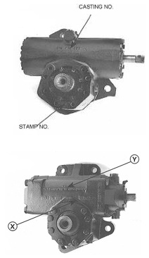
Steering Gear Identification
PREVENTATIVE MAINTENANCE SCHEDULE AND FLUID RECOMMENDATION FOR SHEPPARD POWER STEERING SYSTEMS
Preventive Maintenance should be completed as follows:
- All fluid should be drained from the power steering system. ·
- The steering should be cycled stop to stop to push all remaining fluid out of the gear.
- The filter should be removed from the reservoir and the reservoir thoroughly wiped clean with lint-free rags to remove all the particles too small for the filter to catch.
- A new filter installed in the reservoir.
- The system filled with new fluid per the truck manufacturer’s specification, or 15W40 engine oil if there is nothing else specified. ·
- Bleed any air from the system, check for leaks, and return the vehicle to service.
Basic Steering Gear Operation: Service Bulletin
Power Steering Noise
It is possible to hear an audible hiss at the steering wheel during a steering maneuver.
This noise can be considered normal and does not adversely affect steering performance. Hydraulic fluid operating under high pressure in a steering system can occasionally create turbulence as the fluid passes through the flow orifices of the control valve of the steering gear generating an audible sound in the driver compartment. On occasion, the resonant frequencies of the chassis and steering gear intersect resulting in this audible hissing sound being transmitted through the steering column. Steering output and performance are not compromised as a result of this noise and operation of the steering system will not be affected. In most cases where noise is present in the steering system, the noise is prevalent only at static steer or low-speed maneuver.
Steering noise is not an operational or warrantable repair but is a driver annoyance situation. This noise can be significantly reduced by installing a noise reduction disk, Sheppard Part Number 3331991K, in the return line of the steering gear.
Procedure:
1. Secure the vehicle for servicing.
2. Remove the return line taking care to collect the oil in the drain pan.
3. Remove the return fitting from the steering gear. Note the location of the fitting for reassembly.
4. Install the restrictive disk into the return port of the steering gear using the bladed screwdriver in the slot of the restrictive disk. Turn the disk into the port until it bottoms in the port. Do not overtighten.
5. Install the return line fitting into the steering gear. Locate the fitting to properly align with the return hose. Tighten the fitting and install the return hose
6. Fill the reservoir with an approved fluid, check and correct the fluid level in the reservoir. Start the engine and check for leaks.
7. Lower the hood and remove the drain pan. Should you have any questions about this procedure, please contact Sheppard Power Steering Field Service at 1-800-274-7437.
SEAL KITS
| Sheppard Part Number | International Part Number | Steering Gear Model | Description |
| 5545381 | 2589611C91 | M100-All | Sector Shaft Seal Kit w/ Sector Cover Snap Ring |
| 5544981 | 2585860C91 | M100-Master Only End Cap Seal Kit | |
| 5545221 | 2586318C91 | M100-Master Only | Combined Seal Kit (5544861, 5544881, 5544981) |
| 5545531 | 2592441C91 | M100-Master Only | Combined Seal Kit (5544861, 5545381, 5544981) w/ snap ring |
| 5545441 | M100-Master Only | Combined Seal Kit (5544861, 5545381, 5544981) w/ snap ring and L-seal | |
| 5544951 | M100-Slave Only | Complete Seal Kit | |
| 5545421 | M100-Slave Only | Complete Seal Kit w/ Sector Cover Snap Ring |
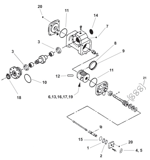
INPUT SHAFT KIT INCLUDES ITEMS 1, 2, 4, 5, 15
COMPLETE SEAL KIT INCLUDES ITEMS 1-21
INPUT SHAFT SEAL REPLACEMENT
TOOLS REQUIRED:
- Drain Pan 15/16”
- 1/2” Drive Socket
- 1/4” Flat Screwdriver
- Seal Pick Rags 1”
- 1/2” Drive Socket
- Small Ball Peen Hammer 5/8”
- 1/2” Drive Socket
- 1/2” Drive Ratchet Handle
- 11/16” Combination Wrench 16mm
- 1/2” Drive Socket 0-100 ft/lb (minimum)
- 1/2” Drive Torque Wrench
1. Remove the steering column lower yoke from the steering gear input shaft using the 5/8” socket and 11/16” wrench. Place the drain pan below the steering gear. Depending on how the gear is mounted, some fluid may be lost.
2. Remove the rubber boot from the input shaft with the screwdriver.
IMPORTANT! CLEAN THE AREA AROUND THE INPUT SHAFT! WARNING! DO NOT TURN THE INPUT SHAFT WITH THE BEARING CAP COVER REMOVED! TURNING THE SHAFT OR MIXING OF COMPONENTS WILL CAUSE DAMAGE TO THE INPUT SHAFT, ROTARY VALVE, THRUST BEARINGS, AND BEARING CAP.
3. Remove the four bolts on the bearing cap cover with the 16mm socket and remove the cover by prying it off evenly with the screwdriver.
CAUTION! THE THRUST WASHER MAY STICK TO THE COVER. IF IT DOES, REINSTALL THE WASHER ON TOP OF THE THRUST BEARING IN THE BEARING CAP.
4. Pry the outside salt seal from the cover with the screwdriver and discard it. Remove the cover washer (if equipped) with the screwdriver.
5. Using the 15/16” socket or seal driver, tap the input (high pressure) seal out of the cover and discard it.
6. Remove the o-ring from the bottom of the cover with the seal pick and discard it.
7. Using the 1” socket or a seal driver, tap the new input seal into the cover with the gold spring facing the bottom of the cover, toward the thrust bearings. A press or vise may also be used.
8. Locate the appropriate size salt seal and tap it into the cover with the 1” socket. Ensure the seal lip or silver spring is facing the top of the cover, toward the steering column.
9. Install the new o-ring onto the outside of the cover. Tap the cover washer back in the cover if equipped.
10. Using #2 chassis grease, fill the area between the seals. No further greasing is required or recommended. If the cover has a grease fitting, remove it and fill the hole with silicone sealant.
11. Lube the o-ring and seal lips with a light coat of grease. Wrap the input shaft splines with tape to avoid damaging the new seals and install the cover onto the bearing cap making sure not to roll the lip of the high-pressure seal. Ensure the small hole in the cover is aligned with the relief plunger screw hole in the bearing cap. Torque the bolts to 53-64 ft/lbs.
12. Choose the correct size rubber boot and install it over the input shaft. Ensure it is pushed down below the bottom of the splines and makes good contact with the cover.
13. Remove the tape from the input shaft and reinstall the steering column lower yoke. Torque the pinch bolt to the manufacturer’s specification.
14. Fill the power steering reservoir to the proper level, start the truck and check for leaks.
IF YOU HAVE QUESTIONS OR PROBLEMS CONTACT SHEPPARD FIELD SERVICE AT 1-800-274-7437
SECTOR SHAFT SEAL REPLACEMENT
TOOLS REQUIRED:
- Drain Pan 5/8” or 3/4”
- 1/2” Drive Allen Socket
- 15/16” Impact Socket Seal Pick Rags Silicone Sealer Impact Wrench
- 1/2” Drive Ratchet Handle
- 1/8” Punch Very Large Snap Ring Pliers
- 13mm 1/2” Drive Socket Medium-sized Hammer
- 0-600 ft/lb Torque Wrench
- 18mm 1/2” Drive Socket
- 1/4” Flat Screwdriver
- Sheppard Pitman Arm Puller 3589922K or equivalent.
1. Park the vehicle on a clean dry surface, shut off the engine and set the parking brake. Place a drain pan under the steering gear.
Note: For steering gear models mounted inside the frame rail or where the pitman’s arm is between the steering gear and the frame rail, the steering gear must be removed from the vehicle for sector seal replacement.
2. Bend the locking tabs away from the pitman arm retainer using the punch and hammer. Remove the retainer using the 5/8” or 3/4” Allen Drive Socket. Remove the pitman arm with the puller, using the 15/16” impact socket and impact wrench.
Only a Sheppard pitman arm puller or a jaw-type puller should be used to remove the pitman arm on snap ring design housings.
CAUTION: Do not attempt to remove the arm by using a wedge between the pitman arm and housing. Housing damage will result! Do not apply heat to the pitman arm!
3. Remove the V-boot from the sector shaft. Remove the snap ring protective cover, if equipped, by carefully prying the plastic seal from the housing with a screwdriver. Take care to not damage the housing during removal. Clean any RTV sealant from the snap ring area.
4. Remove the stick-on plastic dust cover or metal hub cap from the backside of the housing if equipped.
5. Carefully clean any paint or corrosion from the housing to allow the cover to slide freely out of the housing. Remove the snap ring using a suitable size pair of snap ring pliers or “walk it out” with a pair of flat-bladed screwdrivers. Remove the retaining clips and bolts (with 13mm socket), if equipped, or the bolt-on cover (with 18mm socket) as required.
DANGER: The snap ring can slip off of the pliers when removed from the housing. Take care when removing the snap ring as a personal injury can result.
6. Start the truck and allow the circulating pressure of the system to push the sector shaft to cover out of the housing. Shut off the engine when the cover exits the housing. You may start two bolts on bolt-on covers to ensure the cover does not completely exit the housing. A slide hammer may also be used to remove the sector shaft and cover, or the cover and shaft can be driven out of the housing from the opposite side of the steering gear is removed from the vehicle.
CAUTION: Do not turn the steering wheel while removing the cover! Increased pressure from turning can cause the cover to be forced out causing personal injury.
7. Remove the sector shaft and cover from the steering gear housing.
8. Remove the sector shaft seals from the housing and cover using the seal pick. Carefully pry the pressed in excluder from the cover with the screwdriver, taking care not to damage the housing surface.
9. Remove the O-ring from the sector shaft cover or the 2 piece L-seal from the housing.
10. Install 1 new sector shaft seal in the sector cover and 1 new sector shaft seal in the housing. Install the sector shaft seals so the black side (pressure seal) faces the inside of the steering gear. Lubricate the seals with clean chassis lube after installation.
CAUTION: The sector shaft oil seals are two-piece seals. It will be necessary to bend the seals to install them. Set one side of the seal in the groove, and walk it in using your fingers. When the seal is in place it may be necessary to work the seal with your fingers or a blunt seal pick to properly seat the seal. When using a seal pick to seat the seal, push only on the body of the seal and not on the seal lip. Damage to the seal lip will cause an oil leak. The seal should look perfectly round when installed.
NOTE: All snap ring style gears will utilize the thicker O-ring supplied or the 2 piece L-seal.
11. Install the new O-ring on the sector shaft cover taking care not to twist it during installation if so equipped or, install the new 2 piece L-seal into the housing by first inserting the black pressure seal into the housing with the L side facing out. Then insert the flat backup ring into the L side of the pressure seal. When assembled, the backup ring will be on the side of the L-seal facing out. Apply a coat of clean chassis lube to the O-ring or L-seal prior to installing the cover into the housing.
12. Install the new excluder seal into the face of the sector cover by tapping it into place with the hammer.
13. Install the sector shaft into the housing. Take care to align the timing mark on the sector shaft with the timing marks on the piston.
Failure to align the timing marks will result in an incorrect turn radius.
14. Install the cover over the sector shaft. Light hammer blows will be required to install the cover.
CAUTION: Use only enough force to install the cover. Excessive force on the cover could damage the sector shaft cover or bearing and steering gear damage will result. The cover must be installed to flush or below the snap ring groove in the housing on the snap ring and clip retained covers.
15. Install the snap ring or install the cover retaining bolts or retaining clips with bolts in bolt-on cover designs. Torque the cover bolts to 72-87 ft/lbs and clip bolts to 31-38 ft/lbs.
DANGER: The snap ring can slip off the pliers when removed from the housing. Take care when installing the snap ring as a personal injury can result.
DANGER: The snap ring must be fully seated in the snap ring groove. Improperly seated snap rings can come out without warning! Loss of steering control, an oil leak or personal injury may result.
16. Install the snap ring protective cover into the housing over the snap ring by lightly tapping on the outside diameter of the cover until it bottoms in the bore. It may be necessary to tap on the body of the cover with the punch and hammer to fully seat the cover.
17. Pack the V-boot with clean chassis lube and slide the V-boot over the sector shaft splines until the lip contacts the sector shaft cover. On models with a groove cut into the sector shaft under the splines using the boot which has one lip larger than the other, the larger lip should be facing the pitman arm. Slide the boot on until it snaps into the groove. Clean all excess grease from the sector shaft splines.
18. Attach the new frame side dust cover by cleaning the housing with a solvent and applying the new disk over the sector shaft bore with a small bead of RTV silicone on the edge of the disk. Apply a bead of silicone inside the edge of the housing before installing the hub cap.
19. Install the pitman arm by aligning the timing mark on the arm to the timing mark on the end of the sector shaft. Ensure the splines of the arm and shaft are clean and dry. Screw the retainer in making sure the tabs on the washer sit into the grooves machined into the pitman arm. Torque the retainer to the value stamped on the face of the retainer. Keep applying torque until the locking tabs on the washer align with the slots in the retainer. Bend the lock tabs into the retainer.
WARNING: Proper installation of the pitman arm is critical. Improper installation of the arm can cause an accident at a later date. DO NOT BACK OFF WHEN TIGHTENING RETAINER!
20. Fill the system with approved fluid. Start the engine, check and correct the fluid level. Check for leaks. Bleed the system if necessary. Refer to the Sheppard Power Steering service manual #1000400 for the proper bleeding procedure. Return the vehicle to service.
END CAP SEAL REPLACEMENT TOOLS REQUIRED:
- Drain Pan 1/8”
- 1/4” Flat Screwdriver
- Vice Grip Locking Pliers
- Rags
- Seal Pick
- Small Ball Peen Hammer 11/16”
- Combination Wrench 5/8”
- 1/2” Drive Socket
- 1/2” Drive Ratchet Handle
- 2-7/8” Combination Wrenches 16,18,21 or 24mm
- 1/2” Drive Socket 0-300 ft/lb (minimum)
- 1/2” Drive Torque Wrench
- Place a drain pan under the steering gear.
NOTE: Auto Plunger steering gears may require part number 18212821K if the plunger is damaged during disassembly or reassembly. CYLINDER HEAD:
1. Mark the cylinder head and housing for alignment. Remove the four large bolts from the cylinder head using a 16, 18, 21 or 24mm socket. Remove the cylinder head.
2. Remove the square ring and tetra seal from the cylinder head with the seal pick and discard.
3. Remove the relief plunger and replace the o-ring supplied in the kit. Manual plungers can be unscrewed using a flat-bladed screwdriver. AUTO Plungers must be disassembled (flange nut removed from the plunger) and the plunger pushed out of the cylinder head or cartridge. Replace the o-ring, coat with clean chassis lube and install the plunger back into the cylinder head or cartridge. Apply lock-tite to the plunger threads and tighten the flange nut against the spring pin.
NOTE: You will need to check and correct the relief plunger settings after repair.
4. Clean the cylinder head using a suitable solvent. Install the square ring or o-ring in the groove of the cylinder head and install the tetra seal in the small gland of the cylinder head. Apply a light coat of clean chassis lube to hold the seals in place during installation.
5. Install the cylinder head onto the housing, taking care to align the marks made during disassembly. Ensure that the tetra seal aligns with the tube of the housing.
6. Torque the bolts to the spec listed on the next page of this instruction.
BEARING CAP:
1. Mark the bearing cap and housing for reassembly. Remove the lower u-joint from the steering gear input shaft using the 5/8” socket and 11/16” wrench. Remove the hoses and fittings using the 7/8” wrenches and vice grip pliers (if required for removing clamps).
2. Using the 16, 18, 21 or 24mm socket remove the four large bolts from the bearing cap.
DO NOT REMOVE THE BEARING CAP COVER AROUND THE INPUT SHAFT.
Turn the input shaft and raise the bearing cap of the housing until it stops so the seal can be accessed.
3. Using a seal pick, remove the square ring or o-ring and tetra seal from the bearing cap and discard.
4. Carefully stretch the square ring or o-ring over the bearing cap assembly. It can be warmed under hot water to allow it to stretch easier. Take care not to overstretch the seal. With the seal over the bearing cap, push the square ring or o-ring into the seal groove of the bearing cap. Use clean chassis lube to hold the seal into the seal groove. Install the tetra seal in the smaller groove of the bearing cap and lightly coat the seal with clean chassis lube.
5. Remove the relief plunger and replace the o-ring supplied in the kit. Manual plungers can be unscrewed using a flat-bladed screwdriver. AUTO Plungers must be disassembled (flange nut removed from the plunger) and the plunger pushed out of the cylinder head or cartridge. Replace the o-ring, coat with clean chassis lube and install the plunger back into the cylinder head or cartridge. Apply lock-tite to the plunger threads and tighten the flange nut against the spring pin.
NOTE: You will need to check and correct the relief plunger settings after repair.
6. Turn the input shaft into the steering gear taking care to align the marks on the housing and bearing cap. Take care not to pinch the seals during assembly.
7. Install the four attaching bolts and torque to specifications listed in this instruction.
8. Install the u-joint following the vehicle manufacturers’ guidelines. Start the vehicle. Check and correct the fluid level in the system.
9. Check and correct relief plunger settings as required.
TORQUE SPECS AND SOCKET SIZES FOR BOLTS ON ALL D-SERIES AND M-SERIES SHEPPARD STEERING GEARS_
| APPLICATION | SIZE | GRADE | FT/LBS | (NM) | SOCKET |
| Bearing Cap Cover Bolts-All D&M Series | M10 X 1.5 | 10.9 | 53-64 | (72-87) | 16mm |
| Bearing Cap Bolts – | |||||
| M100 | M14 X 2.0 | 8.8 | 114-140 | (154-190) | 21mm |
| Cylinder Head Bolts- | |||||
| M100 | M14 X 2.0 | 8.8 | 114-140 | (154-190) | 21mm |
| All M100 Bolt-On Sector Cover Bolts | M12 X 1.75 | 9.8 | 72-87 | (97-118) | 18mm |
RELIEF PLUNGERS
A relief plunger is placed at each end of all Sheppard steering gears (with the exception of slave gears) to unload steering system pressure prior to the axle stops contacting the axle. One is located in a small hole in the bearing cap cover next to the input shaft. The other plunger is on the opposite end of the steering gear and may be in a hole in the cover, in the hole at the end of a boss sticking out from the cover, or in a cartridge screwed into the cover. The plungers prevent the power steering pump from operating at maximum relief pressure at the end of steering travel. When properly adjusted, the relief plungers reduce system temperature and excessive stress on the mechanical components of the steering system by preventing the axle stops from contacting the axle under full pump pressure.
CAUTION: Failure to set or adjust the relief plungers could result in damage to the steering system. Plungers MUST be set or adjusted whenever a steering gear is replaced.
AUTO PLUNGERS
1. AUTO plunger gears are identified by the word AUTO in raised letters cast into the side of the steering gear housing and plastic caps on each end of the gear covering the plunger hole.
2. Raise the steer tires off the ground.
3. Start the engine and let it run at idle speed. Ensure the axle stops are set for maximum wheel cut with a minimum of 1″ clearance between the tire and any part of the chassis.
4. Set the AUTO plungers by turning the steering wheels from side to side until the axle stops contact the axle. This allows the piston in the steering gear to contact the AUTO plunger assembly and push it back to its set position. The stops MUST contact the axle.
5. Set the vehicle back on the ground. Turn the steering wheel completely from stop to stop. The chassis should not flex when the steering reaches the end of travel. If it does, the AUTO plungers must be reset. Normally you will see a small gap between the axle stop and the axle.
6. Reset AUTO plungers by tapping them in with a 1/4″ punch and hammer until you feel the plunger bottom out in the bore. Be careful not to score the plunger bore. Scoring the bore will cause a leak that cannot be repaired. After the AUTO plungers are reset, set them by following steps 2 through 4. Once the relief plungers are set, no further adjustment is necessary unless tire size or wheel offset is changed.
MANUAL PLUNGERS
1. Your steering gear has manual plungers if you can back them out of the plunger hole with a small flat-bladed screwdriver.
2. Manual plungers are turned all the way in from the factory for minimum wheel cut. Adjust the plungers in to decrease wheel cut, adjust out to increase wheel cut. Use a long, flat-bladed screwdriver.
3. Start the engine and let it run at idle speed. Ensure the axle stops are set for maximum wheel cut with a minimum of 1″ clearance between the tire and any part of the chassis.
4. With the full weight of the vehicle on the ground, have a helper turn the steer tires full left. Check the gap between the axle stop and the axle on the left steer tire. If it is greater than 1/8″ adjust the plunger out (counter-clockwise). Adjust the plunger at the end of the gear which the piston has moved toward. If the stop is touching the axle try turning the plunger in then recheck it.
NOTE: The plungers are fine thread so it may take several turns to get them properly adjusted. Do not back the head of the plunger out past flush with the end of the hole. The plunger could be ejected from the gear.
5. After making an adjustment, center the steering and recheck the gap at the axle stop.
6. When the steer tires have been turned back and forth about 4 times, the rubber will accumulate under the tires and make setting the plungers difficult. Roll the vehicle ahead or back about 1 foot and recheck the gap at the axle stop.
7. Turn the steer tires full right and adjust the opposite plunger for the gap at the right side axle stop using the same procedure. Once the relief plungers are set, no further adjustment is necessary unless tire size or wheel offset is changed.
STEERING GEAR INSTALLATION INSTRUCTIONS
This Sheppard Power Steering Gear has been manufactured and tested for proper operation prior to shipment. Every effort has been made to ensure that it will provide you with many miles of trouble-free, safe operation. To protect your investment and comply with your warranty, it is important that these instructions be closely followed.
1. Anytime a power steering gear or power steering pump is replaced, the oil and oil filter in the power steering system should be changed. All lines and fittings should be flushed of any possible contaminants. Use the type of fluid specified by the vehicle manufacturer or 15W40 Engine Oil if none is specified.
2. If a power steering pump has been replaced, it should be tested to ensure that its pressure and oil flow are the same as originally specified by the vehicle manufacturer.
3. Transfer the hose fittings from the old steering gear to the new one. Replacing the o-rings is recommended.
4. Install the steering gear on the vehicle, care should be taken to ensure the mounting bracket or steering gear is not distorted when the bolts are drawn up. This condition could cause binding in the gear.
5. Attach all hoses to the gear or gears. Ensure they are in good condition and routed with no kinks in the line. Refer to the Sheppard Service Manual for proper routing of dual steer systems. On M-Series gears, the inlet and outlet ports are staggered. The inlet port is always the one closest to the output shaft.
6. Install the steering column or intermediate shaft to the steering gear input shaft, ensure the clamp bolt is torqued to the vehicle manufacturer’s specification.
7. Install the pitman arm using the guidelines in this instruction. Take care not to move the arm more than 2 inches in either direction until the draglink has been installed. Over-traveling the piston will prematurely set AUTO relief plungers.
8. Install the drag link on the pitman arm (except slave gears) and torque the fastener to the vehicle manufacturer’s specification. Slave gears should not have the draglink installed until the Bleeding procedure.
NOTE: If you cannot turn the steering all the way until the stops contact the axle in each direction with the steer tires off the ground, the pitman arm may be mistimed.
9. Fill the power steering system with approved fluid. Start the engine and let it idle.
DO NOT ALLOW THE RESERVOIR TO RUN DRY!
10. IMPORTANT!
Set the AUTO relief plungers or adjust the manual relief plungers to obtain proper wheel cut. Use the guidelines in this instruction.
11. Bleed the gear or gears using the guidelines in this instruction.
12. Double-check all fasteners, fittings, hose routings, and check for leaks. Top off the power steering system and return the vehicle to service.
13. Sheppard recommends the power steering system fluid and filter be changed in accordance with the vehicle manufacturer’s schedule for preventive maintenance. Regular preventive maintenance is essential to extended steering system life. If you have questions at any time, contact our Field Service Hotline at 1-800-274-7437.
RELIEF PLUNGERS
A relief plunger is placed at each end of all Sheppard steering gears (with the exception of slave gears) to unload steering system pressure prior to the axle stops contacting the axle. One is located in a small hole in the bearing cap cover next to the input shaft. The other plunger is on the opposite end of the steering gear and may be in a hole in the cover, in the hole at the end of a boss sticking out from the cover, or in a cartridge screwed into the cover.
The plungers prevent the power steering pump from operating at maximum relief pressure at the end of steering travel. When properly adjusted, the relief plungers reduce system temperature and excessive stress on the mechanical components of the steering system by preventing the axle stops from contacting the axle under full pump pressure.
CAUTION: Failure to set or adjust the relief plungers could result in damage to the steering system. Plungers MUST be set or adjusted whenever a steering gear is replaced.
AUTO PLUNGERS
1. AUTO plunger gears are identified by the word AUTO in raised letters cast into the side of the steering gear housing and plastic caps on each end of the gear covering the plunger hole.
2. Raise the steer tires off the ground.
3. Start the engine and let it run at idle speed. Ensure the axle stops are set for maximum wheel cut with a minimum of 1″ clearance between the tire and any part of the chassis.
4. Set the AUTO plungers by turning the steering wheels from side to side until the axle stops contact the axle. This allows the piston in the steering gear to contact the AUTO plunger assembly and push it back to its set position. The stops MUST contact the axle.
5. Set the vehicle back on the ground. Turn the steering wheel completely from stop to stop. The chassis should not flex when the steering reaches the end of travel. If it does, the AUTO plungers must be reset. Normally you will see a small gap between the axle stop and the axle.
6. Reset AUTO plungers by tapping them in with a 1/4″ punch and hammer until you feel the plunger bottom out in the bore. Be careful not to score the plunger bore. Scoring the bore will cause a leak that cannot be repaired. After the AUTO plungers are reset, set them by following steps 2 through 4.
MANUAL PLUNGERS
1. Your steering gear has manual plungers if you can back them out of the plunger hole with a small flat-bladed screwdriver.
2. Manual plungers are turned all the way in from the factory for minimum wheel cut. Adjust the plungers in to decrease wheel cut, adjust out to increase wheel cut. Use a long, flat-bladed screwdriver.
3. Start the engine and let it run at idle speed. Ensure the axle stops are set for maximum wheel cut with a minimum of 1″ clearance between the tire and any part of the chassis.
4. With the full weight of the vehicle on the ground, have a helper turn the steer tires full left. Check the gap between the axle stop and the axle on the left steer tire. If it is greater than 1/8″ adjust the plunger out (counter-clockwise). Adjust the plunger at the end of the gear which the piston has moved toward. If the stop is touching the axle try turning the plunger in then recheck it.
NOTE: The plungers are fine thread so it may take several turns to get them properly adjusted. Do not back the head of the plunger out past flush with the end of the hole. The plunger could be ejected from the gear.
5. After making an adjustment, center the steering and recheck the gap at the axle stop.
6. When the steer tires have been turned back and forth about 4 times, the rubber will accumulate under the tires and make setting the plungers difficult. Roll the vehicle ahead or back about 1 foot and recheck the gap at the axle stop.
7. Turn the steer tires full right and adjust the opposite plunger for the gap at the right side axle stop using the same procedure.
Once the relief plungers are set, no further adjustment is necessary unless tire size or wheel offset is changed.
BLEEDING AIR FROM STEERING GEARS
Most single steering gears can be bled simply by turning the steering wheel all the way from stop to stop after the gear has been installed, lines connected, the system filled with fluid, and relief plungers set. Some gears, however, require bleeding through a bleeder screw or in the case of dual gear systems, a special procedure. The following guidelines can be used.
SINGLE GEAR SYSTEMS
If the gear is mounted with the bulge in the housing for the sector shaft hanging below the piston-cylinder:
1. With the weight of the vehicle on the ground, start the engine and let it run at idle speed.
2. Turn the steering wheel lock to lock 3 times. Hold the wheel in pressure for about 5 seconds when you reach the lock position in each direction. Center the steering, bleeding complete.
If the gear is mounted with the bulge in the housing for the sector shaft sitting above the piston-cylinder:
1. Locate the bleeder plug on the sector housing. It will look like a bolt head that a 3/4″ wrench would fit. There will be a piece of tape on it covering a 1/8″ allen set screw in the center of it. Remove the tape to expose the set screw.
2. Do not remove the bleeder screw from the plug. There is a check ball behind it that likes to get lost.
3. With the weight of the vehicle on the ground, start the engine and let it run at idle speed.
4. With a helper, turn the steering wheel to the full left. Open the set screw in the bleeder plug 4 turns. With the bleeder still open, turn the wheels all the way to the right. When you get all the way to the right, shut the bleeder. Turn the wheels all the way to the left and repeat the procedure 2 more times. The bleeder should only be open when turning right. If it is open when turning left, air will be forced back into the system. Center the steering, bleeding complete.
DUAL GEAR SYSTEMS
1. With the weight of the vehicle on the ground, start the engine and let it run at idle speed. The draglink should be connected to the pitman arm on the main gear but not connected to the salve gear.
2. Turn the steering wheel all the way to the left until the axle stop contacts the axle and hold until the pitman arm on the slave gear moves its full travel. It should move in the opposite direction of the pitman arm on the main gear.
3. Now turn the steering wheel all the way to the right until the axle stop contacts the axle and hold until the pitman arm on the slave gear moves its full travel.
4. Repeat the procedure 3 more times or until there is no air in the system and the slave gear moves freely.
NOTE: Do not move the pitman arm on the slave gear by hand. Air may be drawn into the system.
5. Turn the steering wheel until the pitman arm on the slave gear lines up with the draglink and install the draglink.
6. Cycle the steering from stop to stop. If a catch is noted, look for bleed plugs on the steering gears. If the gear is mounted with the bulge in the housing for the sector shaft sitting above the piston cylinder, follow the procedure outlined for bleeding a single gear with the bulge in the housing for the sector shaft sitting above the piston cylinder. If both gears have bleeder plugs, bleed only when turning the steering wheel to the right.
NOTE: Do not allow the reservoir to run dry at any time. Bleeding is complete when the steering operates smoothly from lock to lock in both directions.