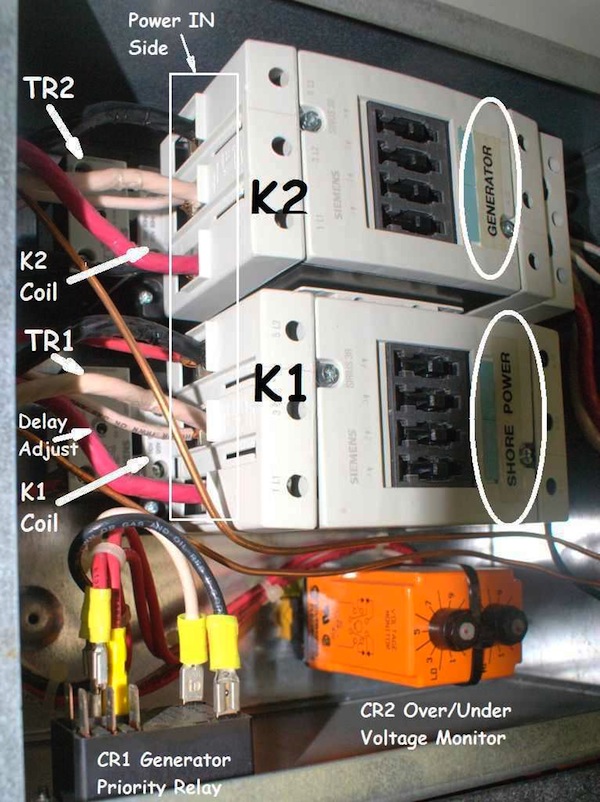
By Dick S. 2003 U320 40′
Here is what happened, what I found and what I did.
1. We suddenly lost the 120 Volt shore power.
2. I found power at the pedestal, but not at the ATS (Automatic Transfer Switch). But, thanks to Barry B, I discovered I was looking for voltage on the wrong side of the ATS. Ok, I did have power to the ATS. That was my first mistake.
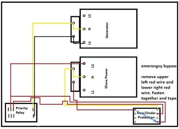
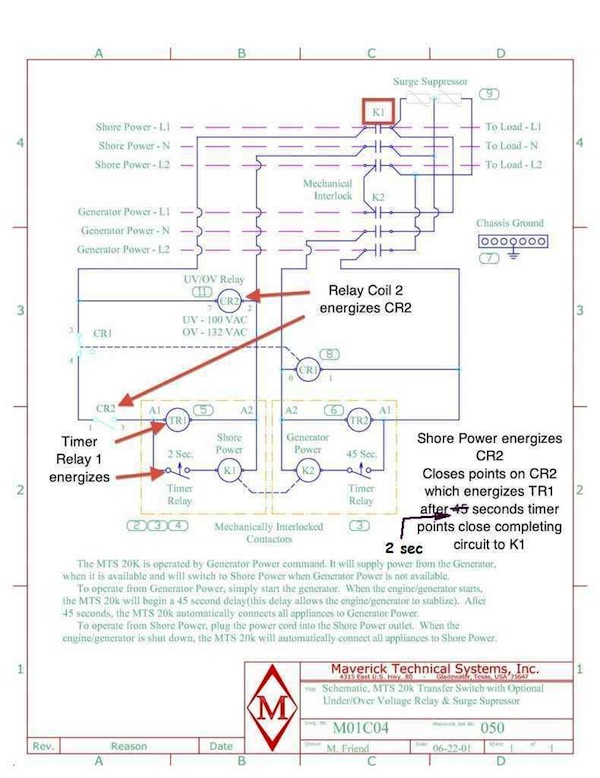
3. This drawing from Barry helped me understand the wiring diagram that is on the inside of the ATS cover.
4. A phone call to James T. at Foretravel gave me some clues.
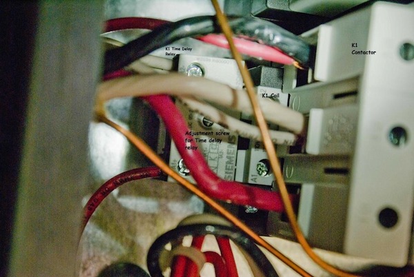
a. James told me that they have seldom had problems with the main contractors, K1 & K2 (big Siemens’ relays that pass Shore Power and Generator Power on to the coach), in this ATS (Maverick MTS 20K).
b. They have had problems with CR2 (the orange over/under voltage monitor relay,
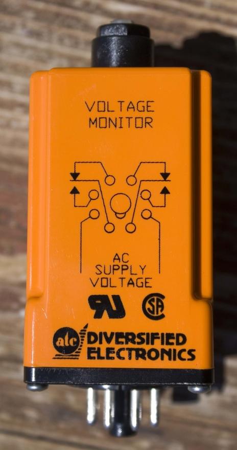
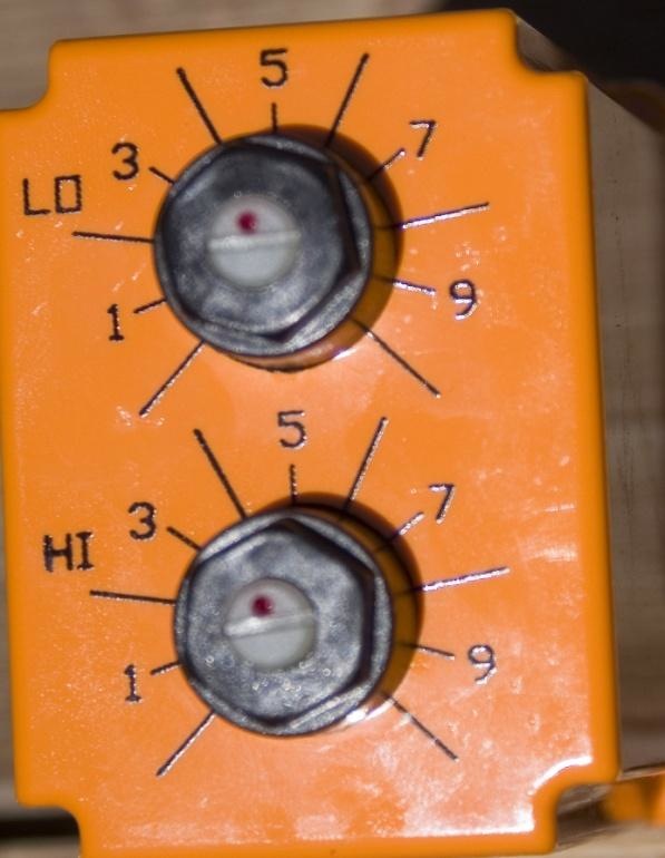
c. This relay has potentiometers for adjusting the LO and HI voltage cutoff values James suggested adjusting the Low down and the High up, if necessary all the way to the stops.
d. These adjustments did not help. I reported that to James and he said I could jumper around this relay. I did and the big contactor, K1, pulled in and we had shore power!
5. After emails to my engineer son-in-law, it turned out I had not bypassed CR2 quite correctly! That was my second mistake and that is why I am not showing that photo.
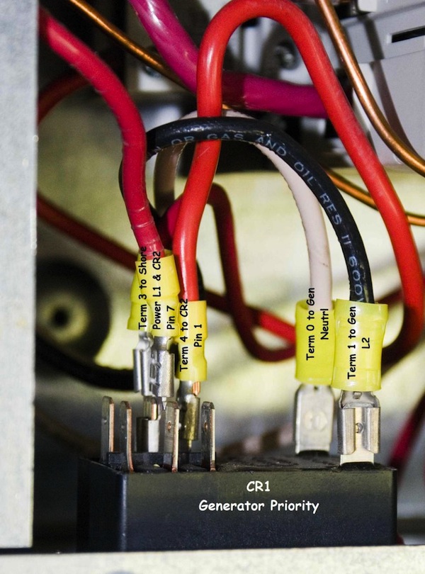
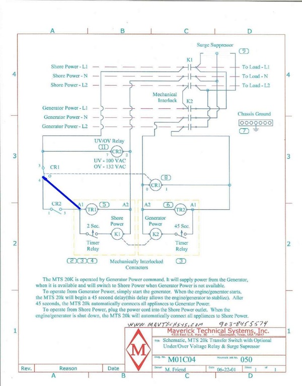
6. So I bypassed it again. But first decided it was necessary to weld the Shore power L1 wire to the floor of the ATS box. That caused the breaker on the pedestal to trip! So, I chipped that loose and replaced the fried connector. My third mistake! (I’m sure glad things don’t come in fours!) Anyway, this is how it is now (Figure 3) and it works fine. Notice that only the normally open contacts of CR2 are bypassed. This proves that the coil of CR2 is energized, but it is failing to close the contacts when the jumper is removed. If I need to start the generator CR1 will still do its job, opening the normally closed contact of CR1 disabling shore power and continuing to give preference to the generator, which is the design of this ATS. This also confirms that the contacts of CR1 are still normally closed, which also indicates that CR1 is not the problem.
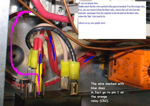
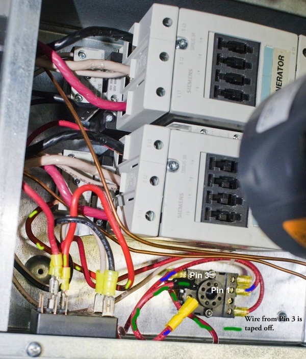
The problem was indeed the orange relay CR2 which monitors over/under voltage, which I ordered from eBay for $61.35 including shipping charges of $11.36. Here are the manufacturer and part number: DIVERSIFIED VBA-120-ALA VOLTAGE MONITOR RELAY 8 PIN.
After installing the new CR2 relay, I adjusted the LO & HI set points (Figure 2 above). I started by setting them to the values used on the old one as shown.
I turned the LO pot up until K1 opened and we lost power. This would have been about 120 VAC since our pedestal voltage is 118 on one leg and 122 on the other. There was still room to turn this pot a little further before it hit the stop.
I turned the HI pot down and down and down to the stop. We still had power. I suspected my eBay purchase. Was this my fourth mistake? I think not.
From the Diversified Electronics web page, I found the information in Figure 6. Note that the “Pick-up Over Voltage” range is 120-150. Our supply voltage is about the same as the low end of that range. And what is this “Hysteresis Voltage”? Figure 7 helps. For example, if the over-voltage set point was 120, this relay would “Pick-Up” at 120, but would not “Drop Out” until 125; the pick-up plus the hysteresis voltage.
So, without a higher supply voltage, there is no way to adjust the over-voltage set point. I will leave it the same as the one I removed for now.
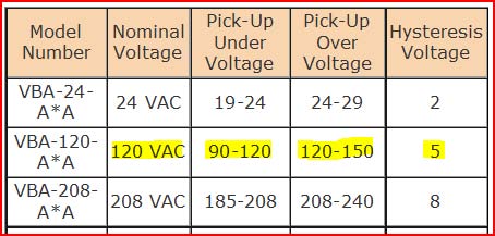
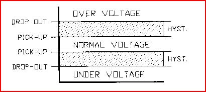
I also learned a couple of other things about this relay from talking to Dale Mayer, Applications Engineer at Diversified. Response time is 50 mSec. from the time it receives voltage. The Release time is 500 mSec. or ••• second. This will allow for voltage “sags” like starting an A/C without losing power to the entire coach.
