by Leese Neville
It is recommended that brush inspection be completed every 12 months beyond the original in-service date on all applications except the school bus. School bus applications should be inspected every 24 months from the in-service date.
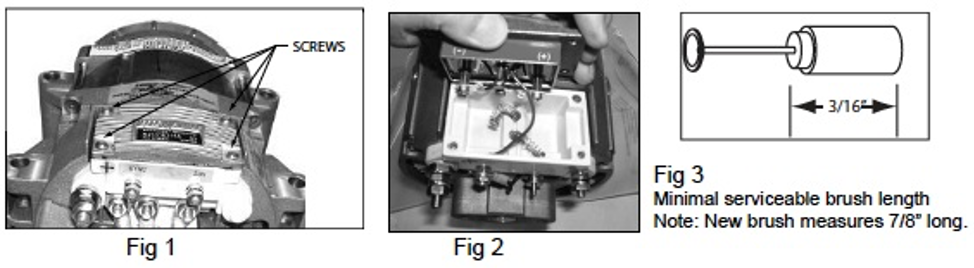
1) Remove 4 screws that attached the regulator to the alternator (Fig 1).
2) Lift regulator from the alternator. (Fig 2).
3) Remove brushes from the brush box and inspect length. If brush length is 3/16” or less then brushes need to be replaced (Fig 3).
Note: If brushes are within specifications note the orientation so they can be reinstalled in the location they were removed.
4) Reinstall brushes into brush holder. If existing brushes are reinstalled after inspection make certain to match wear pattern to slip ring (Fig 4). With brush placed into holder compress entire spring into the holder and retain brush contact into the opening with a 1/16” drill bit or mechanics wire. Install second brush following the same procedure; slipping retaining pin forward through the front opening of the brush box to secure both brushes. (Fig 5).
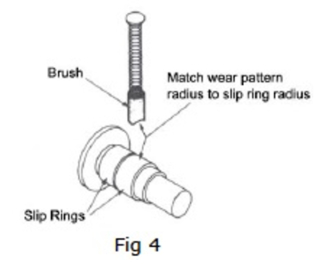
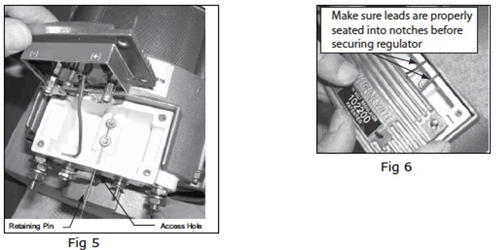
5) Place the regulator back onto the alternator. Use caution not to pinch regulator sense wires (Fig 6). Apply a small amount of downward pressure on the regulator and remove the retaining pin (Fig 5) from the Acess Hole to release the brush springs. Hold down the regulator and secure it with 4 #8-32 screws. Torque screws to 11-13 LB-IN (Fig 1).
If the alternator fails to operate after the brushes are replaced a bad connection between the brushes and the regulator may be the problem. The procedures below will determine if this is the problem.
Internally Regulated Alternators
1) The engine must be off to conduct this test.
2) Make sure the voltage is present at the alternator output terminals. Voltage should be 11.3V or greater if not charge batteries before proceeding.
3) Insert 1/16” drill bit or mechanics wire into alternators full field access hole. Insert straight into the hole until it stops about 1/4” (Do Not Force). Hold firmly in place to ensure appropriate contact. Refer to Fig 5 on page two for the location of this hole.
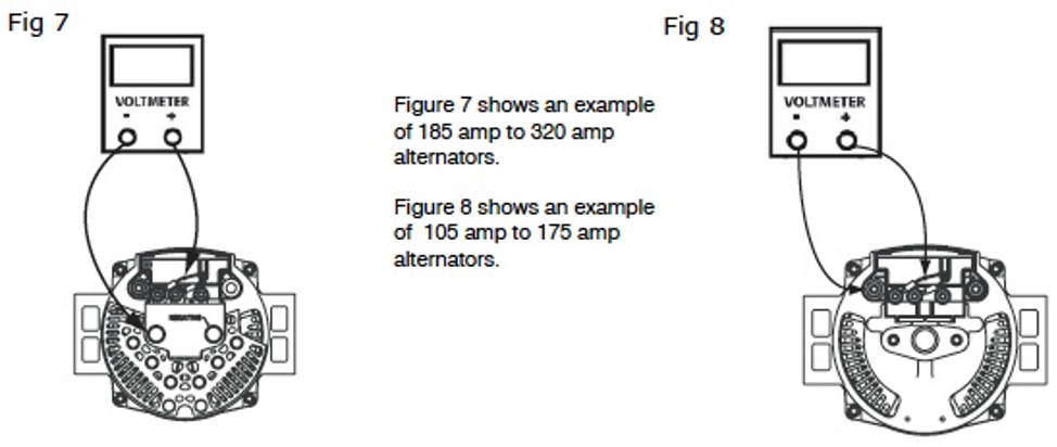
4) Determine which type of alternator you have and connect voltmeter or test light per the diagrams below. One lead of the voltmeter gets connected to the 1/16” drill bit inserted in the alternators full field access hole. The other lead gets connected to the alternator ground terminal (Fig 7,8). If voltage is present or the light illuminates then the connection between the brushes and the regulator is good. If not, then the regulator will have to be removed and inspected for possible contamination between the brushes and regulator. Note: It may be necessary to clean the regulator brush contacts with #600 grade or finer sandpaper.
Remote Regulated Alternators LN-614 regulator
1) The engine must be off to conduct this test.
2) Make sure the voltage is present at the alternators output terminals. Voltage should be 11.3V or greater; if not, charge batteries before proceeding.
3) Connect a jumper wire from the alternator Positive (+) post to the Field Positive (F+) terminal. Connect voltmeter or test light per Fig 9.
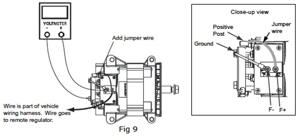
4) If voltage is present or the light illuminates then the connection between the brushes and the regulator is good. If not, then the regulator will have to be removed and inspected for possible contamination between the brushes and regulator.
Note: It may be necessary to clean the regulator brush contacts with #600 grade or finer sandpaper.
5) Remove jumper wire when the test is complete.
Remote Regulated Alternators 8RD2041 or 5078R
1) The engine must be off to conduct this test.
2) Make sure the voltage is present at the alternator output terminals. Voltage should be 11.3V or greater; if not, charge batteries before proceeding.
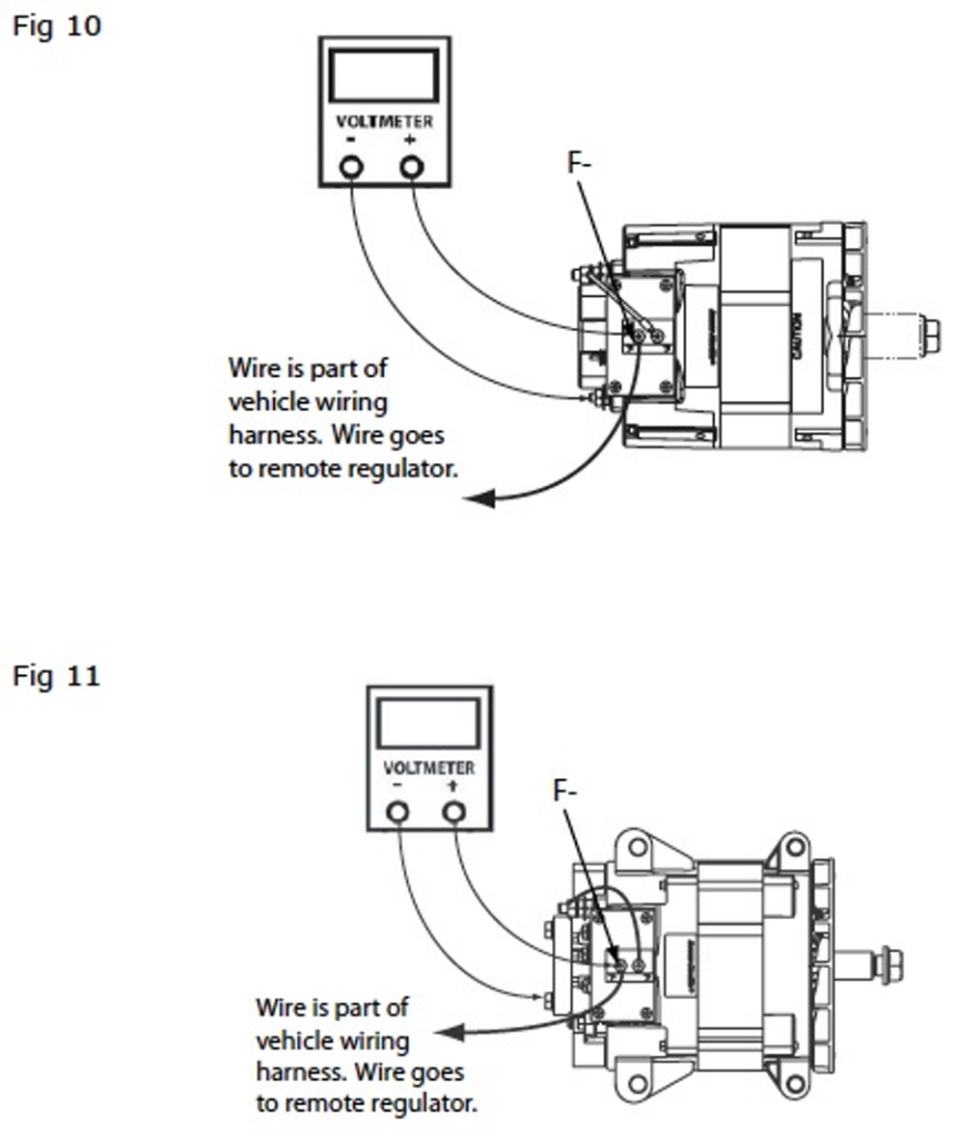
3) Determine which type of alternator you have and connect voltmeter or test light per the diagrams below. One lead of the voltmeter gets connected to the alternator F- terminal and the other lead gets connected to the alternator ground terminal (Refer to Fig 10, 11). If voltage is present or the light illuminates then the connection between the regulator and brushes is good. If not, then the regulator will have to be removed and inspected for possible contamination between the brushes and regulator.
Note: It may be necessary to clean the regulator brush contacts with #600 grade or finer sandpaper.
Important: The information contained in this bulletin is intended for use by trained, professional technicians who have the proper tools, equipment, and training to perform the required maintenance described above. This information is NOT intended for ‘do-ityourselfers’, and you should not assume that this information applies to your equipment.
If you have any questions regarding this information please visit our website at www.prestolite.com, or contact our technical service department at (866) 288-9853 or [email protected]