CHECKS:
• Complete the checks in the sequence listed.
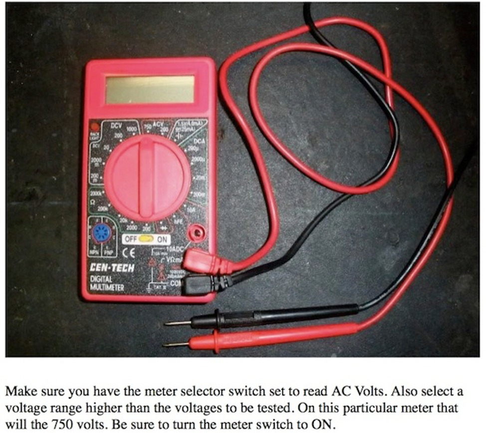
• The meter you are using to conduct these checks MUST be set to measure AC volts (DC will NOT work!).
• The voltage range must be set to 300 VAC or higher.
• It makes no difference if the black or red probes are reversed when checking AC voltages.
• Carefully push the metal tip of the probe into the outlet slot. It may be necessary to angle the tip to make contact with the outlet’s inner metal pieces.
• Be careful testing the outlet as lethal voltages are present on the test leads and probes.
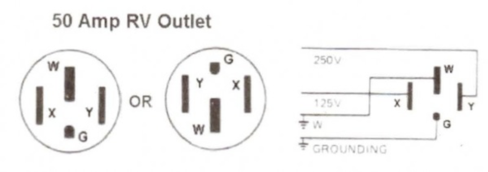
1. X to W should = 110 to 125 Volts to PASS. No Voltage indicates open Neutral or Open Hot. DO NOT use this outlet.
2. Y to W should = 110 to 125 Volts to PASS. No Voltage Indicates open Neutral or Open Hot. DO NOT USE THIS OUTLET IF THIS CHECK FAlLS
3. X to Y should = 220 to 250 Volts. A PASS for this check Indicates that the outlet has the proper phase relationship for both of the 120-volt power feeds. If the voltage IS 110 to 125 between X and Y and both checks 1 & 2 are “PASS”, this outlet is NOT wired for 50-50 Amp Service.
OUTLET MAY BE SAFE TO USE IF ALL OTHER CHECKS ARE “PASS” BUT THE AVAILABLE AMPERAGE WILL BE REDUCED BY 50%
4. G to W should = ZERO volts to PASS. If voltage appears here outlet IS unsafe, most likely a hot and neutral are reversed.
DO NOT US.E THIS OUTLET IF THIS CHECK FAILS
5. X to G should = 110 to 125 Volts to PASS. If check$ 1, 2 and 4 are “PASS” and no voltage appears here, GROUND is Open.
DO NOT USE THIS OUTLET IF THIS CHECK FAILS
6. Y to G should = 110 to 125 Volts to PASS. If all of the above tests are “PASS” and no voltage appears here. GROUND is Open.
DO NOT use THIS OUTLET IF THIS CHECK FAILS
NOTES:
The 110 to the 125-volt range may actually vary between 105 and 130 volts depending upon the time of day (Utility & Park loads vary), The Ideal range is between 110 and 125 volts.
Voltages between 100 and 109 may be used but the risk of damage to equipment with electric motors (air conditioners) is increased.
Other equipment and appliances may not operate properly or as efficiently.
Voltages over 125 volts and up to 130 volts increase the risk of damage to appliances that use resistance elements such as toasters, coffee pots, electric heaters, hairdryers and an RV refrigerator running on electric power.
Voltages between 130 and 135 drastically increase the risk of damage to ALL RV equipment. DO NOT use power from any source if voltage exceeds 135 as damage will definitely occur!
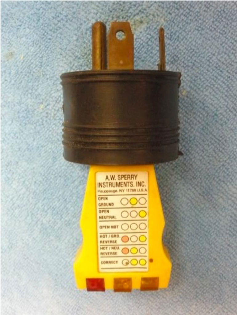
The procedure above using a voltmeter is ONLY for a 50 amp park outlet – for a 30 amp park outlet try the following:
I advise testing 30 amp park outlets with a 30 to 20 amp adapter and a quick check illuminated circuit tester rather than a meter.
The tester shown here was $5 at Wal-Mart and the adapter about $6 at an RV store.
THIS SETUP IS ONLY FOR TESTING 30 AMP OUTLETS – IT WILL NOT WORK WITH A 50 AMP OUTLET
Barry Beam
We made a campground outlet tester years ago and use it at EVERY campground before we plugin. We have Progressive EMS hardwired, but still, use it all the time.
You could use meters into each outlet if you use a 3-gang box or 2 single boxes separated with a spacer, to spread out outlets.
We did ours differently.
I have a 2-gang box with a duplex outlet on one side and a regular 3-way switch on the other side. Two neon lights directly wired to each hot leg and neutral tell me if a leg is hot. One neon light directly wired to each hot leg tells me if we have 220 volts.
Common on 3-way switch is to duplex outlet, both still ganged together. One side of 3-way switches it to the red leg, another side to blackleg.
I have a common AC polarity tester (yellow with 3 neon light) plugged into one of the duplex outlets. I have a limited-range 120-volt meter plugged into the other duplex outlet.
Input cable is a 50-amp male plug with a pigtail on other end, available from Camping World.
Flip switch to read polarity and volts on each leg. On 30 or 20 amp we step down the 50-amp male and only need to test one side of the switch.
I did buy a 30-amp male and female pigtail cords from Camping World and cross wire the black & white-hot & neutral to correct an outlet that had its hot and neutral miswired. Used it twice.
Also have used a spike to make our own ground connection when connected to an outlet that did have a ground.
But 99% of the time all is well. Sometimes voltage is low. Mostly if things are not good, we move on. Barry & Cindy 1997 Foretravel U270 36′
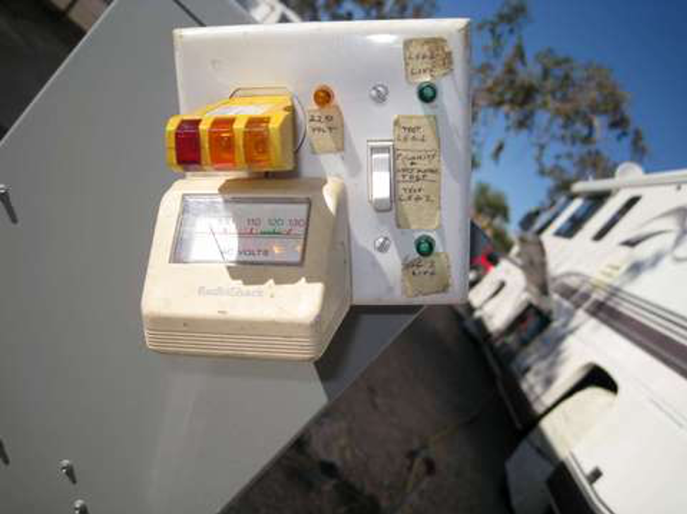
UPDATE: For about 10 years, I have been using a test box that I made with one outlet which I switched between each 50-amp leg. In the outlet, I had one voltmeter and one polarity tester.
Yesterday,
I made an improved version that does the same thing, but without a switch.
I bought two limited-range $15 volt meters in Quartzsite for this project.
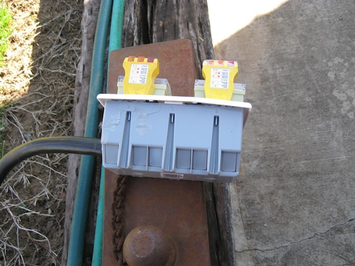
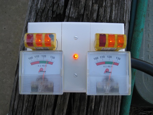
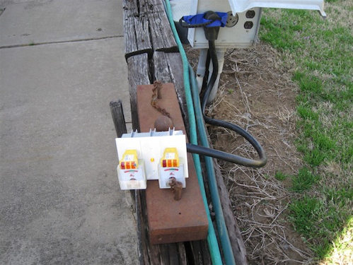
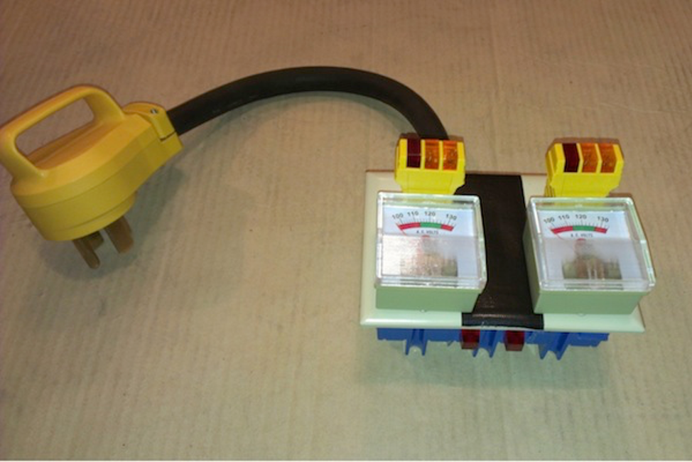
I made this tester with two outlets so I can see both leg voltages and polarity at the same time.
Wiring was simplified with two outlets. I wired a 120/240-volt neon lamp to the two hot cables which will light up only with 240-volts.
Since the voltmeters were too wide to fit in a dual electric box, I used a triple electric box and custom box cover components
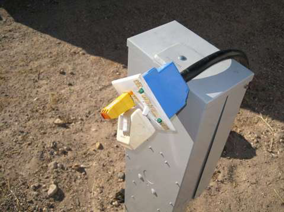
Here are photos of my ‘new & improved’ campground electric tester.
Barry & Cindy 1997 Foretravel U270 36′
I was able to build one of these testers without too much trouble. 50-amp Tester
It seems to work as described. I was able to find most of the parts at the local Home Depot but had to get the voltmeter and voltage indicator on-line. Here are the two sources for those parts.
GB Electrical ET6102 Twin Probe Voltage Tester
The trickiest part for me was going from the #6 wire in the pigtail to the small (#14 or #16) wire used to connect everything in the box. I did this by cutting about 3/8″ bare on each of the four wires. Then on each, I split the wire insulation on either side for another 1/2″ or so and carefully peeled it back. Then I cut about half the #6 wire strands out. That left enough to connect to one end of a #10-12 crimp butt connector (yellow). I then folded the insulation back over the thinned wire and attached the connector to the remaining wire. The folded back insulation was then trimmed such that it fits up against the butt connector. I used heat-shrink tubing to cover the folded back insulator and most of the connector. Then I connected a length of #14 or #16 wire to the connector and heat sealed that. I found some good heat seal tubing at one of the auto parts stores in town. This provided a solid joint. I didn’t want any problems while working with 220 volts!
The total cost was about $60. George Hatfield 2003 U295 36′
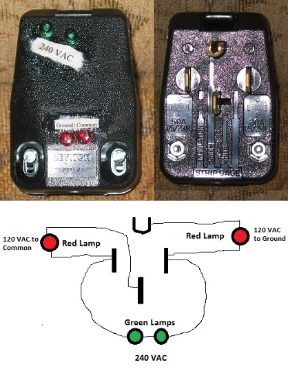
I used a 240 VAC 50 Amp plug from Ace Hardware and two Red & two Green 120 VAC indicator lamps from Radio Shack to build this test unit.
If both green lights & both red lights illuminate all is OK You have a true 50 Amp, 240 VAC service.
If only The two red lights illuminate you Do Not have true 50 Amp service You have 50 Amp, 120 VAC.
If only The common red lights illuminate you Do Not have true 50 Amp service and it is dangerous to use this service.
If only The ground red lights illuminate you Do Not have true 50 Amp service and it is dangerous to use this service.
50 Amp RV are wired to use 240VAC at 50 Amps this gives you the 120Vac at 100 amps total. If you are using a service that is 50 Amp 120VAC then you can only use 50 Amp total. If you exceed 50 Amp you can burn up the common (white) wire in your RV. I hope this will help you, if you have questions I can be reach [email protected] If you want to talk send me your number and I will call you as soon as I can.
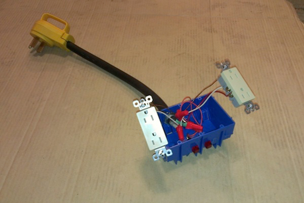
My son and I decided to put together a campground power pedestal tester. This design has been posted before, I made an improvement to use a 3 gang outlet box which allows 2 line voltage meters to be plugged in side by side.
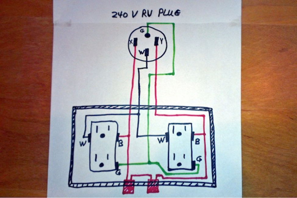
Here are links for the various parts, pictures, and a schematic. I estimate I have about $50 invested, but now I can be sure a 50 amp power pedestal is wired correctly before I plug in my coach. Note the 2 red neon indicators wired across the 240-volt hot leads will detect a “fake” 50 amp power pedestal. If the red lights don’t light up, someone cut corners and only wired the pedestal with 120 volts. In this situation, your coach is only getting 1/2 the power it was designed for, and you run the risk of overloading the white neutral wire in your power cord and coach.
Prime Products 12-4055 A/C Line Voltage Meter
GE 50542 Receptacle Tester, 3-Wire Light Improper Wiring Indicator
Camco® Power Cord Plugs with PowerGrip
Radio Shack 120-Volt Neon Red Square Lamp 2102793

Peter and Tammy Fleming 1991 U300 GV 40′