by Pierce Stewart 1993 U300 36′
Finally had a few minutes to document the 10K generator fuel pressure gauge installation.
This gauge will help diagnose generator problems and will show the procedure for installation.
At first, I thought I could install the gauge on the outlet side without removing the adapter plate but I could not find a fitting to allow the gauge to be placed on the outlet side of the filter without placing a “T” in the fuel line.
The gauge now shows the pressure out of the fuel pump and into the filter BEFORE the diesel is filtered. You can still check for a clogged filter but will have to read on.
To do a neat job, you will need an 11MM brake line wrench to crack the fuel lines. An end wrench will probably not do the trick. I didn’t have one handy so I used a ViceGrip. You can see the marks it left. Remove the fuel lines and then remove the whole assembly by using a 12MM wrench where it bolts to the engine.
I drilled an 11/32 hole as shown in the photo, tapped it with a 1/8″ NPT tap and then installed a 1/8″ riser and 90 degrees fitting on top of that. The center outlet fittings must be removed before the fittings for the gauge can be installed then reinstalled after the gauge fittings are in place.
Unless the filter is recent, this might be a good time to replace it. When the assembly is about to be reinstalled, first install the fuel lines with your fingers. It’s much easier to align the threads if you can easily move everything. Then install the rear 12MM bolts.
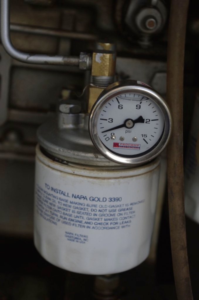
Install the filter hand tight and then loosen the air bleed (14MM) on the top of the filter housing. Put a catch pan under the filter to keep diesel off the engine mount. Hold the glow switch down and you should able to hear the fuel pump clicking. After air bubbles stop, tighten the 14MM air bleed fitting. Turn the air bleed “T” handle upon the top air bleed (photo) counterclockwise until it is all the way out. Push the glow/stop switch again and watch the gauge for a few seconds. It should read about 1 psi as the fuel is returning to the tank without any restriction. Release the switch and turn the “T” handle clockwise until it is all the way in and seated. Hold the switch down again and the pressure should read about 4 psi. If the pressures are equal with the valve open or closed, this indicates the spin-on filter is clogged.
A couple of points:
The top air bleed valve should always be closed (all the way in) during normal generator operation. Otherwise, the generator may quit during high loading such as air conditioner operation. If the valve drips diesel in any position, tighten the nut until it stops. The drip will destroy the rubber mount down below.
Only check engine mount condition with the generator tray pulled out and inspected from the bottom. They may look great from the top.
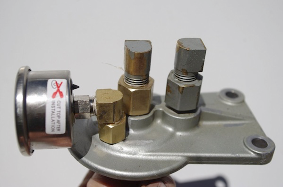
Filter Adapter Plate
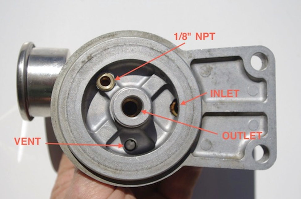
Port Locations
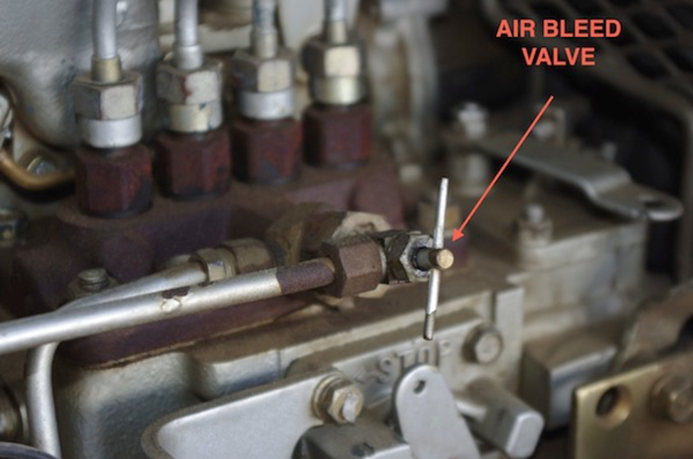
Air Bleed Valve
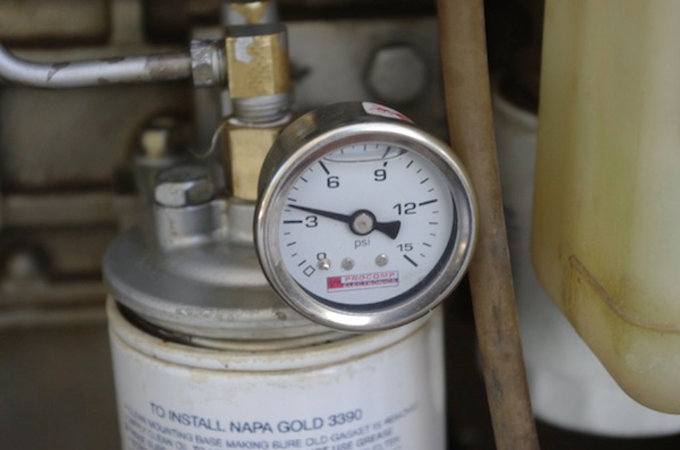
Air Bleed Closed
Air Bleed Open