LEVEL SENSING UNIT ADJUSTMENT
NOTE: The sensing unit has an accuracy tolerance of +/- 1″ side to side and +/- 5.4″ front to rear on a 36’ coach.
If it is determined that the sensing unit needs to be adjusted, contact parts and service for authorization.
The correct method for adjusting the sensor is as follows:
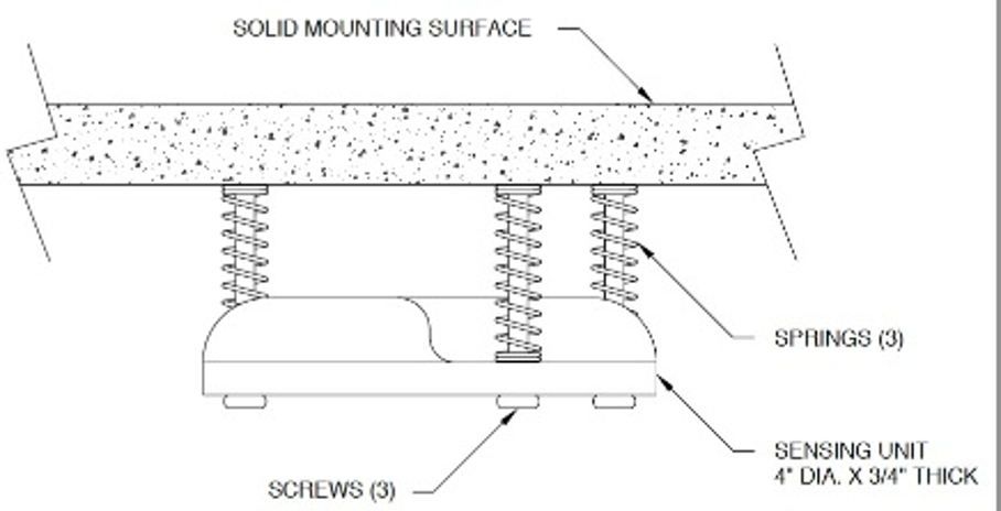
First, level the coach by placing a 24″ level in the center of the coach on the floor. With the coach level, adjust the sensing unit until all yellow lights are out. This is done by drawing up or backing out the sensing unit screws. If a front light is on, adjust the front screw. If a sidelight is on, adjust the side screw. If a rear light is on, adjust the rear screws. One or more screws may have to be adjusted to turn the yellow lights out. After adjustment has been made, pull down on the sensing unit to make sure that the unit is bottomed out on the screw heads. Check to make sure all yellow lights are out. If not, readjust. Rock the coach and recheck for yellow lights. Readjust if needed.
We removed two bottom kitchen drawers and worked on our level sensor that is screwed to the floor under the drawers. First found it was not exactly positioned on a front to back axis.
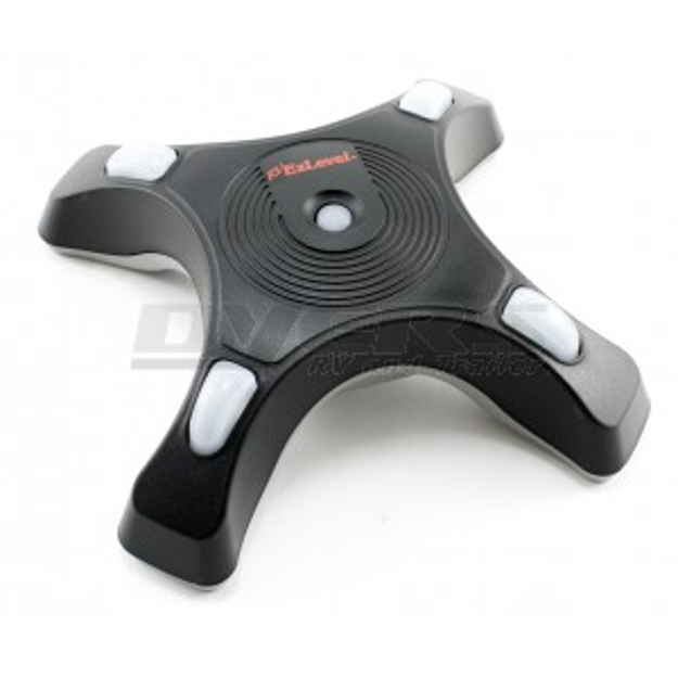
So I remove two screws (beware of springs) and rotated the sensor a small amount and put the two screws in new floor holes. We purchased a four-leg electronic level called RV EzLevel
Then used HWH dash panel buttons to manually level the coach with EzLevel on our wood floor in front of the sink. Watching the HWH panel, I adjusted the 3 sensor screws until the HWH panel showed we were level.
Replacement HWH Electronic level RAP-91031 Barry & Cindy 1997 Foretravel U270 36′
I manually leveled the coach using bubble levels. While my spouse watched the HWH control panel, I tweaked the mounting screws for the sensor with a screwdriver equipped with a square driver. The spouse let me know when the yellow lights illuminated. I worked on a couple of screws that were primary adjustments for fore/aft and left/right. I found the screw positions that caused the yellow “out of level” lights to illuminate. I put the screws in positions near halfway between the “out of level” positions.
I am more content with leveling now that I have tweaked the adjustment. I have a better understanding of the settings and functionality. JDS 1997 U295 36 5/11/10
NEWER COACHES SENSOR LOCATION
SENSING UNIT ACCURACY TOLERANCE
The sensing unit has an accuracy tolerance of ± 5.4 inches front to rear and ± 1-inch side to side on a 36-foot vehicle. Typical leveling results will be better.
Level the vehicle by placing a bubble level in the center of the freezer floor or upon whichever surface within the vehicle that is to be level. Using the Leveling System and the bubble level, ignoring the yellow LEVEL lights on the Touch Panel, level the vehicle until the bubble is centered.
With the vehicle level according to the bubble level, if there are no yellow lights lit on the Touch Panel, the sensing unit is properly adjusted. If there are yellow LEVEL lights lit on the Touch Panel, manual adjustments to the Sensing Unit are needed. A 7/8″, 3/4″ or 5/16″ socket w/driver or box end wrench and a Philips screwdriver will be needed
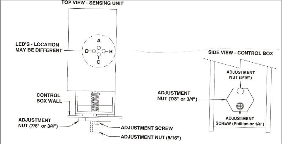
The Sensing Unit is mounted inside the Control Box. The Control Box is mounted to the power unit/valve assembly.
There are four LED’s on the Sensing Unit, A, B, C, and D. Refer to the drawing below. The Sensing Unit is adjusted by turning the adjustment nut to turn out LED’s B and D. The adjustment screw will turn out LED’s A and C. If the adjustment nut has to be turned more than 1/2 flat or the adjustment screw has to be turned more than 3/4 turn to turn the LED out, there may be a problem with the Sensing Unit or the mounting of the Control Box. If two LED’s are on, it is best to make the B-D adjustments first, then hold the adjustment nut from moving MP85.6148 ADJUSTMENT NUT (5/16″) while making the A-C adjustment.
NOTE:
If opposing LED’s are lit, there is a problem with the Sensing Unit.
If LED (A) is lit: Turn the adjustment screw COUNTERCLOCKWISE until the LED is off.
If LED (C) is lit: Turn the adjustment screw CLOCKWISE until the LED is off.
If LED (B) is lit: Turn the adjustment nut COUNTERCLOCKWISE until the LED is off.
If LED (D) is lit: Turn the adjustment nut CLOCKWISE until the LED is off.
IMPORTANT: When all 4 LED’s are off, move the vehicle to an unlevel position so one or two yellow lights are on. Level the vehicle according to the yellow LEVEL lights. Recheck the level. If more adjustment is needed, DO NOT try to adjust the sensing unit until the yellow level lights go out, instead just “tweak” the sensing unit, ignoring the LED’s on the sensing unit.
Example: After the initial adjustment and releveling the vehicle, the front is still low. This means the front yellow level light is turning off too soon. Determine which sensing unit light is the front light, A-B-C or D. Move the adjustment for that light very, very, slightly in the OPPOSITE direction that is given in the above instructions for LED’s A, B, C, and D. This will allow the front yellow light to stay on slightly longer to bring the front up more. Again, unlevel the vehicle then relevel the vehicle using the yellow level lights on the touch panel. Recheck with a level. Repeat the “tweaking” process until the system levels the vehicle properly.
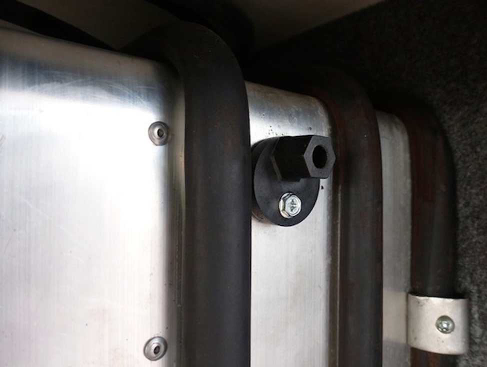
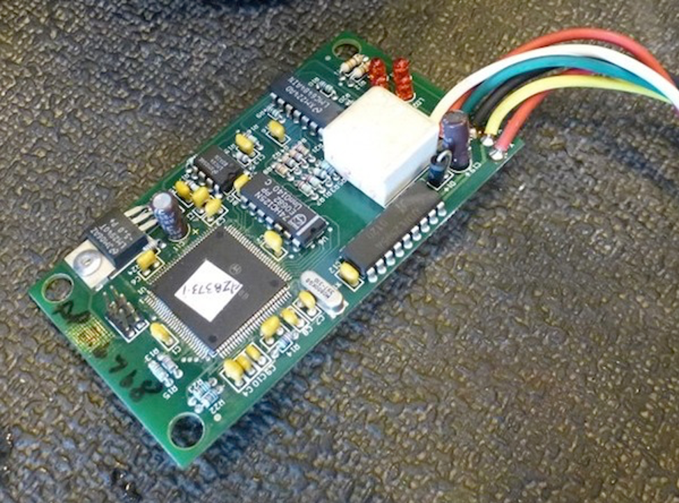
On newer Coaches, the level sensor is an electronic sensor circuit board on the can in the Electronics bay with the adjustment on the outside of the can.