There are still many of you traveling around the country in earlier model coaches that have a Prosine 2.5 Inverter/Charger. These units were installed as original equipment on coach year models 1999 through 2005. If you encounter a fault condition with this particular Inverter/ Charger, here is some information that may be helpful.
When a recoverable fault occurs usually there will be an indication on the Prosine Interior Remote Control panel.
Error Code Displays and What They Mean
Many types of faults are recognized by the Prosine inverter/charger.
Should a recognized fault occur, the fault LED will illuminate and an error code will be displayed. These error codes will override any other menu items being displayed.
The way in which this is done is different for the Standard Control Panel and the Advanced Control System (ACS).
Control Panel
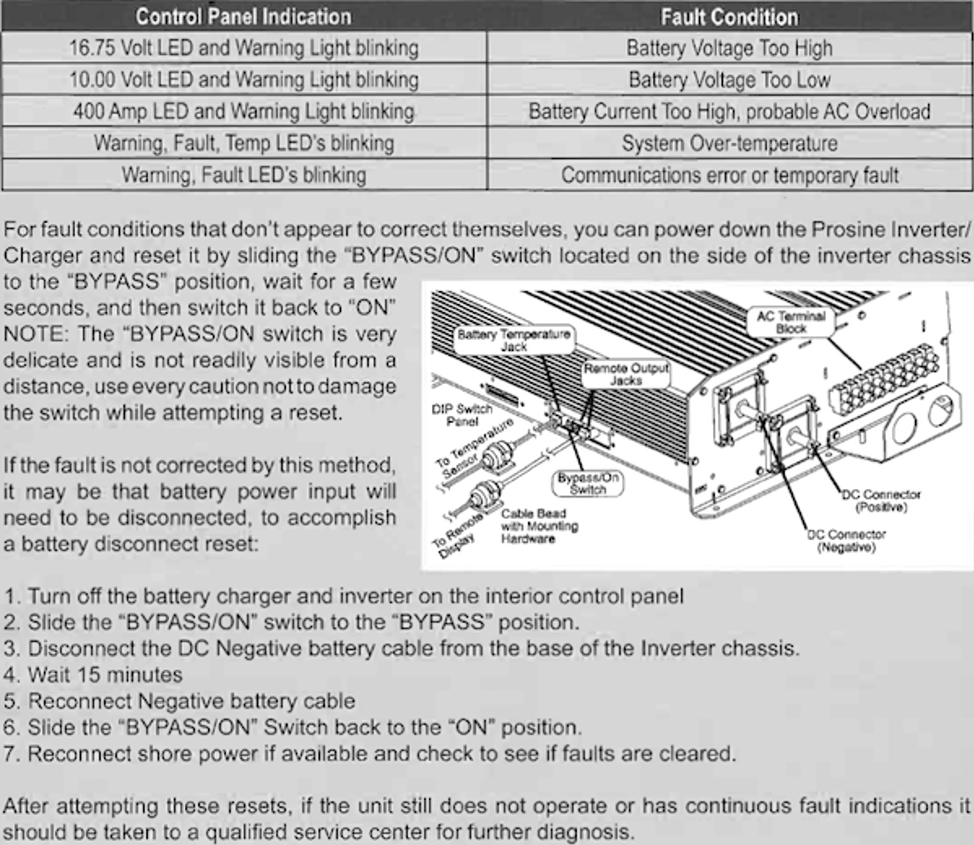
When the WARNING, FAULT, or TEMP LED is on, try to find what is causing the fault condition by following these steps:
1. Press and hold the RESET button to display the error. It takes about five seconds before the code displays.
2. Note the LEDs that illuminate to determine the 3-digit fault code, as in the example below.
3. Look up the error code in the Error Code Table to assist in troubleshooting the fault condition.
While the RESET button is pressed, the 3-digit number is displayed as follows:
1. The first digit is shown in the FAULT section, TEMP = 0, FAULT = 1, WARNING = 2
2. The second digit is shown on the DC VOLTS bar graph, the bottom LED = 0, the second-lowest LED = 1, and so on to the top LED = 9.
3. The third digit is shown on the DC AMPS bar graph, the bottom LED= 0, the second-lowest LED= 1, and so on to the top LED = 9.
When none of the FAULTS lights are on, pressing and holding the RESET switch will display the last recorded fault.