by The Rusty Socket 10/17/15
Over the years, you will run into lots of cooling issues, they can be as simple as a loose fan belt, the wrong radiator cap, not enough coolant in the system or not enough antifreeze mixed with the water to give you your proper boil-over protection.
There can be many other more complicated issues, hoses that look good may collapse when the engine is hot and the thermostat opens when the engine is up to speed, you may have a failed water pump. I have seen a pump with the impeller lose on the shaft. The engine cooled fine at idle but under load and at speed, would overheat in minutes.
But for this paper, let us just look at how a radiator is built.
There are 3 major parts to the radiator.
There are two types of radiators we need to deal with. The vertical flow, which will be the most common and the ones that most people see. And the horizontal flow, like in a Chevy pickup truck.
So for now, let’s just use the vertical flow.
1) Top tank.
2) The core.
3) The bottom tank.
So now, let’s just lump the tanks in together. The top tank will most likely have the radiator cap on it, there might be a separate tank mounted remotely but for now, let’s keep it simple and just go with just the top tank.
There are two types of systems that you will run into. Closed and
open.
When I say open, what I mean is if you take the rad cap off and you can look
down and see the tubes of the core, it is open.
Closed means that if you take the cap off and look down and see just metal with no tubes, it is a tank on top of a tank.
There is an engineering reason for this that I am not going to bother with right now, just be warned that if you are filling the system on a closed system, it can take quite a while to get the system fully filled, just because the top tank seems full, it might not be. So, we are looking at a vertical flow, open system.
Now, there is a difference between an automotive core and an industrial core.
We are going to be looking at industrial applications. automotive tend to run aluminum cores with plastic tanks. Cheaper to replace than to repair, so other than a few pictures, we will just ignore them.
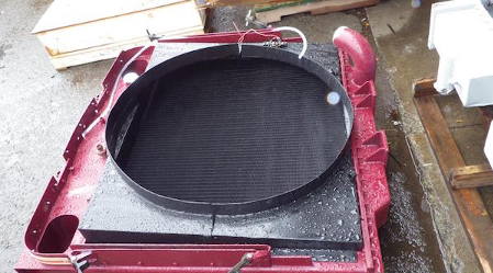
This is a photo of a Pacific P16 Radiator used in the logging industry in British Columbia, mostly in the coastal mountains.
The left side of the photo is the lower tank, the big elbow coming off is for the lower radiator hose.
This radiator has been modified, the big oblong holes in the top tank are to allow the Charge Air Cooler to fit on the front of the radiator and the pipes extend through the holes in the top tank. Esthetically to the eye, but not what I would have done.
This radiator will cool a 600 HP engine very easily.
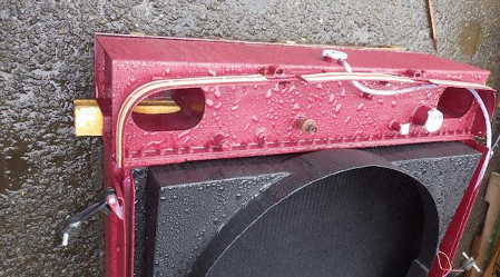
Here is another view of the top tank. You will notice how small the radiator cap looks in comparison to the rest of the radiator. You can see the bolts where the tank is bolted to the radiator core.
The tanks hold a reservoir of coolant in the radiator. So that is what an assembled industrial radiator looks like, let’s have a look at the parts and pieces.
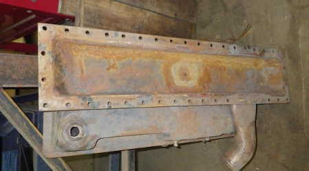
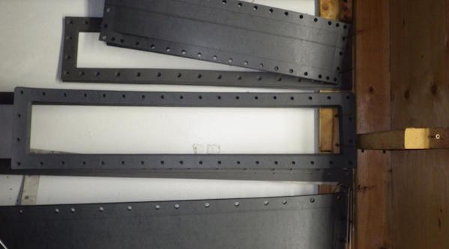
Here is the top tank off of a Kenworth T-800. Unfortunately, I didn’t get any pictures of an open system tank, this is a closed system tank. But for now, this will work. Notice the bolt holes around the edges of the tank. This is where the core will bolt up to the tank.
The bottom tank is pretty much the same, just a tank to store the coolant.
Now, to the heart of a radiator. The core.
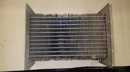
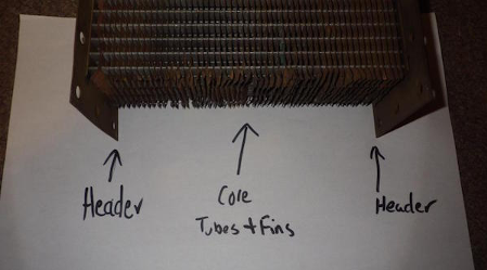
This is a training sample of an industrial core.
The two brass pieces on the left and right side are called the headers, the middle is the fins and the tubes go through the fins. This is called a straight tube core, more on this later.
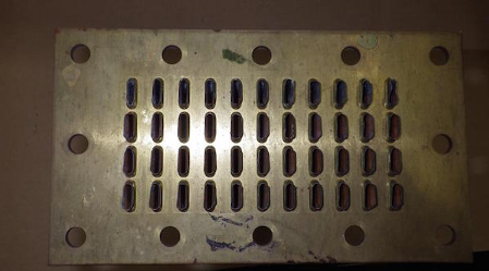
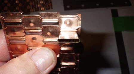
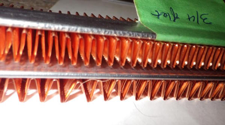
This is what the top of the header looks like. The tubes protrude through the header and are then soldered in place.
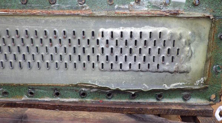
This is a photo of the old core that came out of the Kenworth T-800, here you can see the tubes soldered into the header, notice how they are built up with extra solder for about ten rows and the first two or three rows are blocked off, this is to help strengthen the radiator and to help stop it from leaking at the end rows, a very common problem.
The green looking stuff around the outer edges is the gasket. This radiator has cork gasket tape on it. Old school radiator assembly technic, more on this later.
You can also see that the tubes in this one are staggered instead of the straight tube as in the sample core.
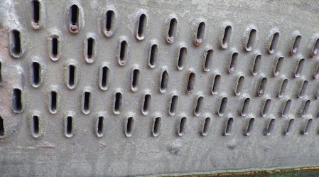
Another photo showing the detail of the tubes soldered into the header. This is a used core that was beyond economical repair, if it had been new it would look much nicer.
So to recap
THE CORE, PARTS, AND NAMES.
So how about a closer look at the parts. I don’t have a sample header, but all it consists of is a piece of brass with holes punched in it. Now there will be several thicknesses of brass that are used, the type of application will dictate the thickness.
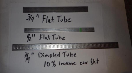
Let’s have a look at the tubes and fins.
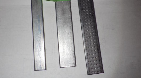
Tubes. The two left ones are just standard tubes, the one on the right is a dimpled tube. We will talk more on this later
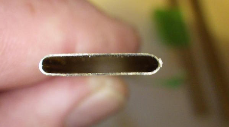
A tube, standard not dimpled
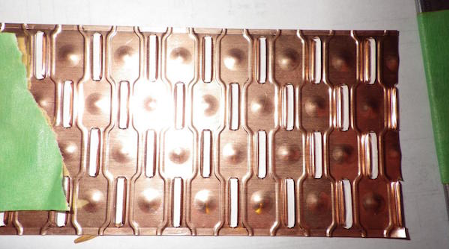
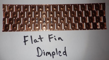
This is a sample of a dimpled fin, the little cut-outs are where the tubes will go through, this is a staggered row.
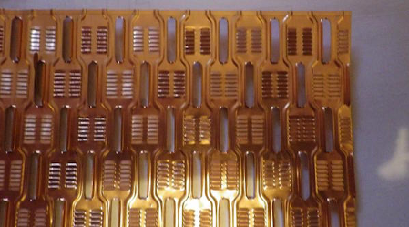
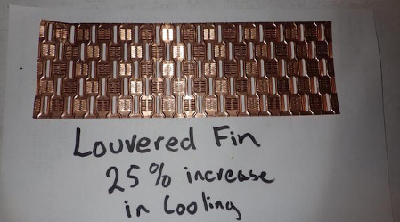
This is a sample of louvered fin
Tube fitting through a piece of dimpled fin
How the tubes fit through the fin.
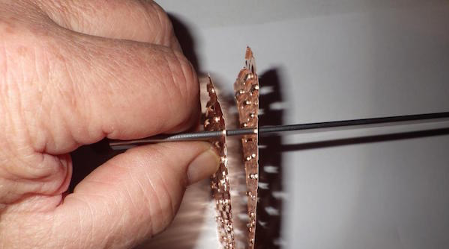
So this is all that there is to the core, tubes, and fins stacked up. The coolant goes through the tubes and the air goes through the fins. Easy?
Now to start getting technical.
So here is the kick.
Straight row rad, dimpled fin, flat tube. Your basic industrial radiator core. Works cool, does what it supposed to do.
Now if you want a rad that will fit in the same footprint but cools up to 40 to 45% better, you go with a staggered row, louvered fin, dimpled tube.
And here is why.
A radiator is a heat exchange unit. We want to take the heat out of the coolant and release it into the air, at the same time we want to take the cool out of the air and put it into the coolant. To do this we allow the coolant to go into the radiator.
So the dimpled tubes will increase the heat transfer by slowing the rate that the water passes through the tube. The longer the coolant is in the tube, the longer it has to cool.
The louvered fins work much the same way. If you look at the picture of the dimpled fin you see the little bump. That bump will cause a disturbance in the flow of air over the fin and tube. The turbulence will allow more heat to exchange. Now the louvered fin will cause even more turbulence so more heat exchange again.
If you go with a staggered row, once again more turbulence so more heat exchange. And that, in a nutshell, is how it works.
Sorry, no little pixie’s with magic wands.
Now, let’s have a look at some of the rest of the construction
In one of the other photos, I showed the old school cork gasket, here is a picture of the new way of sealing the radiators up.
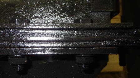
Not a good picture but here we are back at the Kenworth T-880 radiator all assembled and painted
Top tank, gasket, header, and side hanger all assembled and bolted.
Proper formed and punched gaskets, no seams to leak
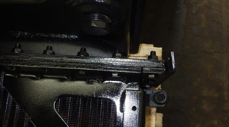
Another picture of the Kenworth T800. Top tank and showing a good picture of the side hanger and the bolting. The side hangers hold it all together and stiffen the radiator up so it cannot flex and crack.
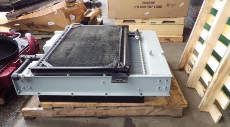
This is a photo of a large industrial radiator with a remote oil cooler mounted on the front. The top radiator tank is on the right side of the picture. Notice how large and robust the side hangers are on this radiator.
Here are some other pictures of tooling used for radiator repair.
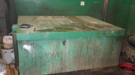
This is “THE BEAST” It is an industrial hot tank. Basically what it is, is a tank full of caustic soda and water (Sodium Hydroxide I believe, could be sodium hydrochloride, my chemistry was way too many years ago). The tank is kept at just below boiling. The components of the radiator are disassembled then put into the tank and boiled for several hours, then removed and washed with a stream of compressed air and water. Everything pretty much comes off, paint, any oils, and grease. It is a nasty thing.
If you put a ham in it and closed the lid, when you came back in the morning there would only be bone. Hence the BEAST!
If you ever decide to use a radiator stop leak product in your radiator, and then you would like to have it repaired. The hot tank WILL NOT remove most of them from the rad core and will in fact contaminate the header so that it is just about impossible to repair. Barrs Leak’s brand is the worst. You put that stuff in and you just bought a brand new core. If you must use a stop leak product, try to get one that is aluminum-based. The caustic soda will react with the aluminum and dissolve it. But depending on the product, it might have other additives that will not dissolve in the caustic.
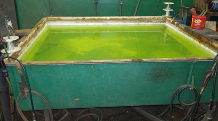
After the radiator is all assembled, it is plugged, filled with compressed air and submerged into a test tank. The green color is an additive that is put into the tank to #1, neutralize the acids used in the making and repair of the core and #2 the fluorescent green color makes it easier to see any leaks that may happen.
Once it is sealed and tight, it will be dried and painted
Now, on to one of the most neglected parts of the cooling system
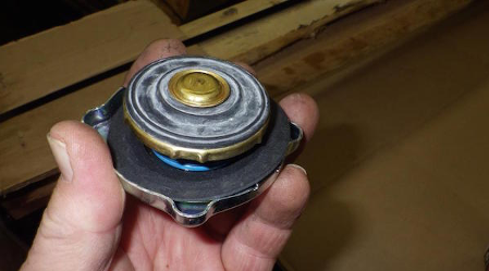
That’s right, the lowly radiator cap.
THEY ARE CHEAP. CHANGE ON A REGULAR BASIS
Now let’s see if I can remember my basic cooling specs from 40 years ago when I did my mechanic training.
If I remember correctly, the boiling point will be raised 2-3 degrees F for every PSI of pressure. A basic industrial cooling system runs a 7 PSI cap, so by having a 7 PSI cap, we can raise the boiling point in the system up 21 degrees to about 243 degrees F.
Also important to have your antifreeze water mixture in the proper proportions, this will give you the maximum boil-over protection.
Not only is this important to avoid boil over, but you do not want cavitation inside your engine, avoiding bubbles inside the engine is a good thing
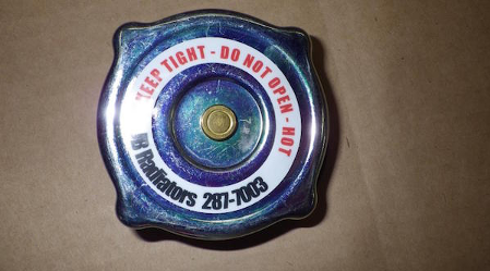
And many thanks to the owner and crew at JB Radiators for all the help getting me samples and taking the time to explain some of the finer points.
Oh, automotive radiators
Pretty much the same, but instead of the tube going through the fins, the fins are folded and attached to the tubes this way. Nowhere near as strong. This is a real copper fin, all the new ones are aluminum, cheap crap.