Slide Creep – is a phenomenon that is best described as: The large slide fully extends and does not remain in the fully extended position and “Creeps” inward 1” to 2”. ( Note: This Slide Creep appears to only happen to the large slide on the 2002 Foretravel using the Type B Train System. We do not know by build #s the introduction of this mechanism or the extent thereof. This paper in no way intends to incriminate either Foretravel for its use of the TRAIN slide system or HWH Corp. for its design, manufacture or sale/distribution.)
Purpose
The purpose of this paper is to familiarize the reader with the TRAIN slide Type B system and to provide some diagnostic and possible repair outlines specifically referred to as “Slide Creep”. Caution: this “creeping” anomaly could cause damage to your air seal bladder if not repaired promptly or operate the slide system and air bladder seal with the greatest of care.
Scope
2002 is a unique year for the large slide mechanism and used a TRAIN slide system. If your coach has a 2nd slide it is not a Train mechanism. It is unknown why Foretravel used this slide mechanism for one year only. Speculation touts “latest and greatest” to HWH moving this slide technology to Foretravel as the only option available – no choice. This system is also used on some Country Coach motorhomes. This Slide Creep” can originate in one of these places: an internal leak in one of the cylinders for that room, check valve, bad manifold or even the solenoid valve. (Note: 2001 & 2002 also had slide Locking Pins that locked in place in the retracted position there-by locking the slide IN or retracted for safe travel.) This paper will focus on the extent and retract solenoids and the internal leak of the lower rear cylinder as looking at the slide from the inside.
Cause – Leaking Cylinder
Brad and other professional Technicians point to the mounting bolts of the dinette in some cases might be too long and create increased pressure on the hydraulic cylinder if the outer Villa dinette tabs are used, as they can easily rub on the Train mechanism as it extends and retracts. This increased pressure may stress the hydraulic cylinder to the point of internal seal failure. According to HWH, the usual culprit is a solenoid valve starting to allow fluid to leak, generally internally in the manifold.
Cause: Leaking Solenoid
Old age
References
- HWH Corp. web site
- Foretravel Owner’s Forum thread entries specifically “Large Slide Moves In” and other web entries as appropriate.
http://www.foreforums.com/index.php?topic=19897.0
- Brad Slaughter, ForeForums Member [email protected]
- HWH Instruction: Room Extension Solenoid Valve Replacement http://www.hwh.com/mi159502.pdf
- HWH Instruction: Cylinder Bleeding Procedure
http://www.hwh.com/ml23527.pdf
HWH Specific Tools
- HWH Isolation Kit – Part #TS42926 (Currently $108.00
- Snap Ring Assembly Tool – TS27333 (Currently $10.00)
- Train Repair Kit – RAP90883 is a link repair kit ($73.00), RAP90826 is a roller repair kit ($35.42).
- HWH Cylinder is labeled AP24220, replacement is #: “RAP90856”. New – $395 – rebuilt – $276 max as of this writing. Note: A local hydraulic shop may be able to repair these cylinders at less cost. Brad’s repair part cost $75.40 and the labor was $67.50 for .75 hrs. All 4 cylinders are interchangeable.
- Link Repair Kit – RAP90883 – $73.00.
- Roller Repair Kit – RAP90826 – $35.42.
- Snap Ring – Rotor Clip – Part # SHM – 25 Web Page: https://www.rotorclip.com/rotor-express.php Part # might be referenced as: SHM-25, SHM-025, SHM-025SA
Retailer Link: https://www.huyett.com/Products/Fasteners/Retaining-Rings/Snap-Rings/SHM-025.aspx
Minimum Order: 15 @ $.1725 ea.
Symptoms
Once the large slide is fully extended it may/will “creep” in anywhere from 1 to 2”. It may be accompanied by a friction “pop(s)” as the sliding skin moves against the air bladder. This slide creep typically occurred most noticeably to the bottom left part of Brad’s slide as you are looking at the slide from the inside of the coach. Throughout the day, you may hear these pops or creaks, as this is not simply a one-step creep. The creep may not even be inconvenient, however, it is placing lateral stress on the air bladder. This can be verified by releasing the bladder and noting that the slide will immediately move further in as the stress of the bladder is released.
While at first, this release/reapplication of the air seal may appear to be somewhat of a solution, the timing of the cylinders is affected and long-term results of that are a slide that does not evenly extend or retract. It is important to note that you cannot tell by just looking whether the cause of the creep is a bad solenoid valve or a cylinder with an internal leak. HWH reports that it is usually a leaky solenoid valve. That is the easiest to change and is the first and easiest item to test for.
The Basics of the TRAIN Mechanism:
The TRAIN mechanisms consist of 4 hydraulic cylinders that extend and retract the large slide. It also has a Synchronizing Cylinder that synchronizes the 4 extend and retract cylinders so they operate equally while extending and /or retracting the slide. It is important to make the mental note that when the cylinders themselves EXTEND, they pull (retract) the slide in. When the cylinders themselves RETRACT, they push the slide out into its extended position. The slide also uses solenoid valves and a computer interface. The drawing below shows the TRAIN mechanism and parts for one train only. ( Note: Any drawing/image that may appear in this paper is for reference only and should not be used to specifically identify/repair your unit.)
TRAIN DRIVE – ROOM EXTENSION ASSEMBLY FOUR-CYLINDER ROOM EXTENSION – WITH SYNCHRONIZING CYLINDER
Short Term Solution
Leave the slide retracted until a repair is affected.
Long Term Solutions
Take to a factory authorized HWH repair facility for accurate diagnosis and repair. Be sure that wherever you take your motorhome to be serviced actually has and will use an Isolation Kit to diagnose the problem. If they do not, they will likely be putting new parts into your coach and hoping it fixes it. There is no way to tell whether it is a cylinder or a solenoid other than using the kit or a similar pressure gauge/valve.
Self-Diagnosis and Repair
The initial diagnosing method is to eliminate the solenoid valve as leaking. To properly diagnose the exact problem one must first acquire from HWH their Isolation Kit. This kit is currently sold by HWH for $108.00 + tax and shipping. Attached to the system, the kit will serve to either verify a leaky solenoid valve, or it will cause you to further diagnose the problem.
Reminder Note: The 4 cylinders are all RETRACTED when the room has been extended.
Solenoid Test Procedure
http://www.hwhcorp.com/ml42737.pdf
Brad S narrative: “First understand that you have a “B” system. The procedure is essentially a reasonably simple 2-person process. Main idea is to take a line off from the manifold with the room in the correct extended position, insert a valve (from the kit) into the line, return the line and valve to the manifold, then have someone hold the extend button and then close the valve with the room fully open and the button held down. Then release the button, disconnect the hose (should be zero pressure), and then connect the 5000 psi gauge to the manifold where the hose was…and then see what happens. If the gauge goes up to 500psi+ over the next few hours, then the cylinder extends valve is the culprit. If not, then one of the other items mentioned above will be at fault. These instructions are printed out and come with the kit.
Brad’s Test Results on his Coach
“…no pressure on the gauge (about 5 hours after hookup), but the lower part of the slide is already in about 1-1/2 fat fingers…likely just short of an inch… after sitting about 20 hours, there is no indication of pressure on the gauge, thus the solenoid does not leak.”
Thus in my case, the solenoid valves turned out to be ok and further testing was warranted. I removed the isolation kit gauge and the valve, and then returned the hose to the manifold as I had found it. There was only a small drip of fluid lost…since there was no pressure.
Brad’s Test Results 2nd Coach–Leaking Solenoid
After leaving the second coach overnight with the slide extended and the Isolation Kit in place, the gauge read 2500 PSI. This clearly indicates that the solenoid is leaking. Also, since the hose is capped and none of that pressure could be used to make the slide creep, the slide remained perfectly extended with no creep at all.
Decision Point:
If the pressure has risen, then you have identified the problem as a bad solenoid valve. Go to that section for the process.
If there is no pressure, then continue with testing and isolating the cylinders.
Solenoid Replacement Procedure
First, we took off the Isolation kit (which was still at around 2200 PSI…so we opened the retract valve and released the pressure), then we installed the new Extend valve (over the top of the reservoir). Probably a total of an hour spent at the coach to remove the isolation kit (which had been left there for approximately 10 days while awaiting the part) and to remove and exchange the solenoid valve.
A couple of lessons learned:
Lesson 1. The LR slide extends valve is THE most difficult valve to get out. It is well tucked away nearest the wall and ceiling of the bay. There is also a fat hydraulic hose running across the top of it that must be lifted up a bit by person #1, while person #2 gets a smallish pair of channel locks around the end of the 1-1/2″ valve. You only get a tiny bit of movement before you run into the ceiling and have to loosen your grip and re-establish it. It was VERY tight at the beginning and stayed fairly tight almost all the way out.
When I replaced the new valve, it screwed in 99% of the way by hand, needing just a nudge with the channel locks to finish it. Looking at the manifold, turning the solenoid body righty-tighty and lefty-loosey is the rule. No odd threading. BTW, as a left-hander, I crawled through from the opposite side of the coach and, laying on my right side, had pretty good access to the valve, both by sight and by feel. I’m thinking it might be more difficult to have to use your right hand.
Lesson 2. When you take apart the electric connector for the solenoid’s wires, BE SURE YOU SOMEHOW MARK THE WIRE CONNECTOR THAT YOU TAKE OFF (a shrouded male connector with 2 pins inside). Because if you do not do so, when you get ready to plug your new valve back in, you will then discover that you have 4 identical connectors there to choose from.
Then you will have to have someone release the bladder, press the extend button repeatedly while another person checks the 8 different pins to determine which of them is carrying power while the switch is pushed. The white connector wires are NOT the ones carrying power as you’d expect. It will be one of the black wires in one and only one connector…while the switch is being held down. What the three EXTRA connectors are for is unknown. This was a U320 with 2 rooms, yet still, the extra wiring was present.
Were it not for the lesson learned in #2 above, we would probably have been done in less than 30 minutes. Now we just have to wait a bit and make sure the creep is all fixed and that there is no secondary issue with a cylinder.
The only other comment to make is that the drawing in HWH’s MR55.2000 shows that new valves have 3 o-rings at the end and 2 o-rings near the body…and the drawing shows more o-rings on the old style valves. That does not seem to be true. Both the new and old valves have the same 3 rings at the end (2 are flat, the middle one is round) and 2 rings (one flat and one round) near the body.
Cylinder Test Procedure
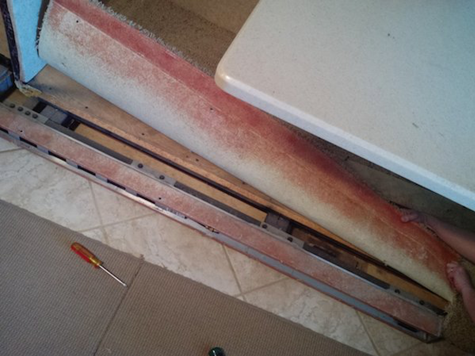
“There are 4 hydraulic cylinders on the large slide. They are each approximately 24” long and they are mounted in aluminum channels. Two are located on the top of the slide behind the header – one on the top left and one on the top right corner(s) of the slide, The two lower cylinders are located behind glued carpeting. One bottom left and one bottom right of the slide.
Remove the slide Header to expose the two top cylinders. Remove the drawers in the dinette and lift up the carpet. The edge of the carpet also needs to be pulled up in front of the couch. The two lower cylinders are behind carpeting that must be pulled up to expose these cylinders.
If your slide has not been worked on before, you will likely have plastic Lexan covers on each aluminum channel. The lower ones will have adhesive, the upper will not. These clear plastic covers may slide out of the mechanism and are not HWH required covers but have been installed for additional protection by Foretravel to keep liquid from getting into the mechanism. The bottom clear plastic covers receive a goodly coating of the spray adhesive to hold the edge of the carpet down.” Foretravel no longer sells replacements. They are difficult to get out and not tear up. If you cannot replace them, it is not really a problem. (My plastics were actually able to be slid back into place without a lot of effort.)
Have the room all the way out and gain access to the bottom cylinders. You will see on the cylinders both a T fitting and a 90-degree fitting that hoses hook up to.
Hit extend and hold it for about three to five seconds after the room is fully extended and then remove the hoses on the 90-degree fittings on each cylinder and cap all the fittings on the cylinders. It is advisable to also plug the lines. These are 1/4” steel flare fittings, caps and plugs.
Then let the room sit for however long it takes for this creep in. You will easily be able to see if a rod has started to extend by itself, as its stop bolt head will have moved away from its stop at the edge of the aluminum channel. ANY rod that shows the movement is showing you that it has an internal leak. Since the four cylinders are now isolated from each other, you will not see a “false problem” of having a single leaky cylinder cause other cylinders to move due to its hydraulic leakage.
When I first observed my rods in the system when everything was still connected, I saw that THREE of the rods actually pulled away from their stops. Using the steel caps completely isolates the effects from one or more bad cylinders making it look like there are more problems. Had I not known that I likely would have allowed a repair facility to replace all three of the cylinders that had moved since I could have easily been led to believe they were all faulty.
Pictures of the top Train/Hydraulic cylinders below:
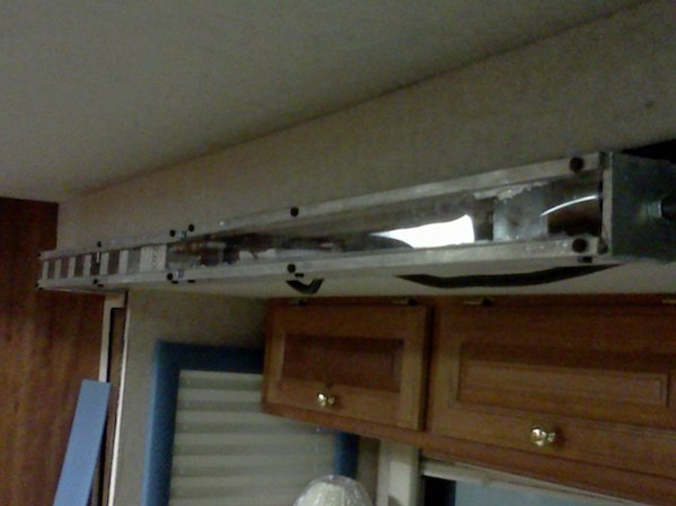
Top Left Cylinder
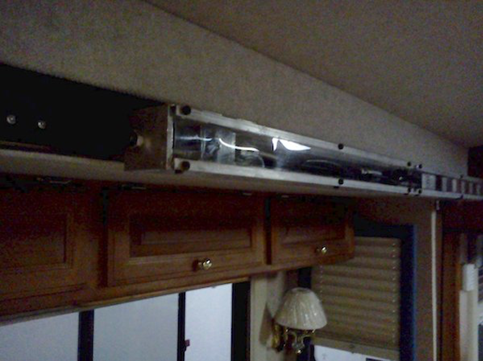
Top Right Cylinder
Brad’s Observation(s), narrative and pics while examining his creep issue. This was WITHOUT having isolated the cylinders with the caps on the 90-degree fittings.
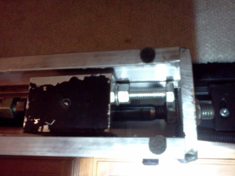
“There are bolts with locking nuts that limit the travel of the Train apparatus as it pulls the rods in (thus extending the slide). All 4 cylinders extended to the limiting bolt heads and stopped as appropriate.
Three hours later, I went out and surveyed the situation. As usual, the rear of the slide had crept in. I measured the distances between the 4 limiting bolt heads and the walls they butt up against. The lower two were approximately .575″ (left) and .500″ (right). The upper left had a gap of about .125″, while the right was still flush and solid. I then released the bladder, so that any resistance it was providing to the creep would be relieved. I then re-inflated and measured again. The upper cylinder distances did not change, but the lower two did. The lower left was now at .750 and the lower right was .650.
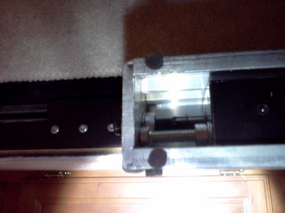
Pictures of the ends of the 4 cylinder rods and the stop bolts are below.
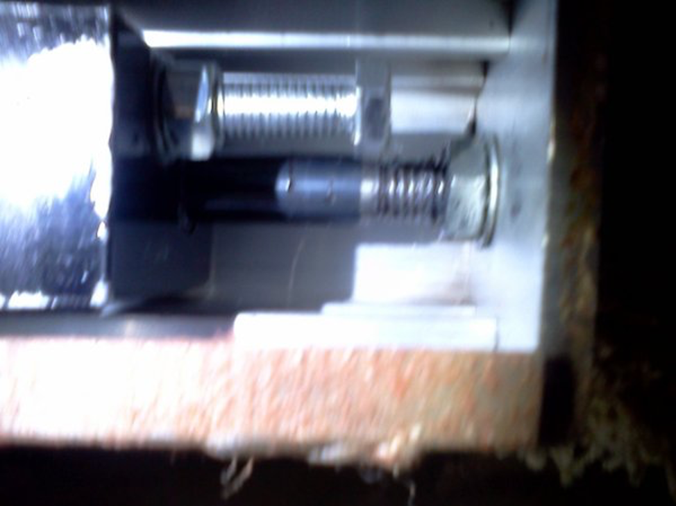
Lower Left
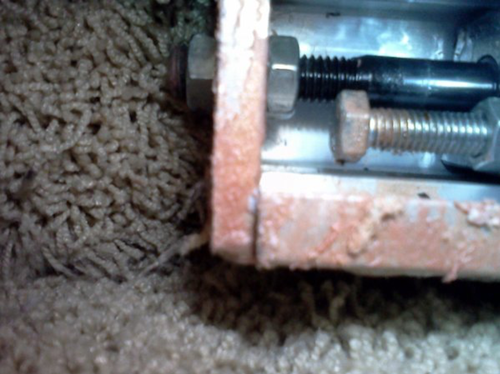
Lower Right
Upper Left
Upper Right
These pictures were taken before the cylinders were isolated and capped. Although my only bad cylinder turned out to be the lower left, it’s pressure leakage in the hydraulic system caused both the upper left and the lower right to push away from the stops. These are false indicators and those cylinders are NOT faulty. You (or a repair facility) cannot test properly without capping and isolating each cylinder.
12 Hours +/- later – The rods (3 of them) had extended further. The top right remains at the stop, and the top left didn’t add too much more spacing, but the bottom cylinders were both near the 2″ mark.
After notifying HWH, I got a response “Yep no question about it you have an internal leak someplace, not sure where but when you get the caps we are going to isolate the cylinders and see if one of those is causing the issue.”
Next step in the testing process-Caps and Plugs:
I got the caps in the mail from HWH. They are regular steel 1/4″ flair caps. I went down to the local “store-with-everything-hydraulic-and-plumbing” and found 4 matching steel plugs. I verified with HWH that plugging the lines that I remove would not impede the testing.
It seemed a cleaner plan than just letting them sit open.
HWH advised that there wouldn’t be any pressure on the hoses, but they should not be allowed to drain by hanging down. Thus I spent $5.00 and bought four plugs for the lines.
HWH told me to start the capping with the cylinders that were showing the most creep (the lower ones). I put a towel down and only lost a tiny bit of fluid.
Once the leaking cylinders are identified, then the caps are to be removed, the lines replaced, and then I’ll retract the slide. It must be in the retracted position in order to remove any of the cylinders.”
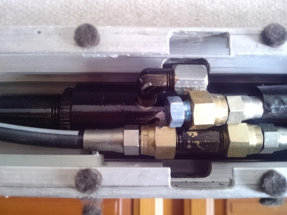
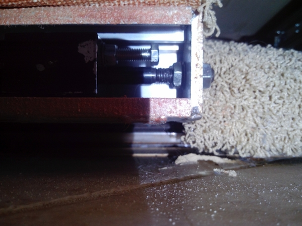
Pictures below tell the story. The first picture shows an example of one of the lines removed (from the 90-degree elbows) and the cap in place on the cylinder and the plug in place on the line. There was minimal fluid leakage in taking the line off. All 4 look the same.
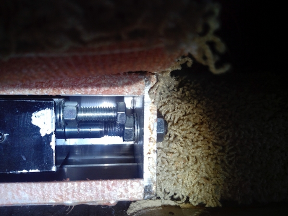
The second picture shows how the cylinder has extended the rod about 1/2″ (measured by how far the stop bolt has moved from the aluminum stop wall, which it was flush against at the start of the test), and it was taken about 30 minutes after starting. The third picture was taken about three hours after beginning the test, and it shows the rod has extended around an inch.
At this point, it is verified that the lower front (which had extended about 1/2 the distance of the rear when it was not capped), and the upper front (which had moved only about 1/16 of an inch) moved only because of the bad lower-rear cylinder.
After concluding which cylinder(s) move, then replace all lines where they belong and bring the slide in. It has to be retracted for cylinder removal. HWH warned me that there will be some pressure in any cylinder found to have moved. I slowly released the cap and there was an initial “psssst” release, but very little fluid actually came out on the paper towels I had there.
Capped and Plugged
30 Minutes later
3 Hours Later
After 6 hours, the other 3 cylinders remained tightly snug as they should have been. So, the most difficult one to get at, the lower rear, is my only culprit with an internal leak-by.
I put the system back together, pushed the extend button for a cycle (a couple of seconds) and the rod went back to the right place. Then I retracted the slide without a problem. The next step is the removal of that cylinder.
REPLACEMENT PROCESS FOR CYLINDER
Lower Rear Cylinder Removal:
The dinette seats (both) do need to come out. Open the slide at this point so you can have a bit of room to work. Unbolt the two seating units from the floor. I turned them upside down on the couch, as you must retract the slide and lose all the space for the next steps. The slide will remain retracted until the repairs are effected.
Once the slide is retracted, the next step is to pull up the carpet across the first approximately 6″. It is mostly held by the same adhesive as on the front, but there were a few staples also in my carpet.
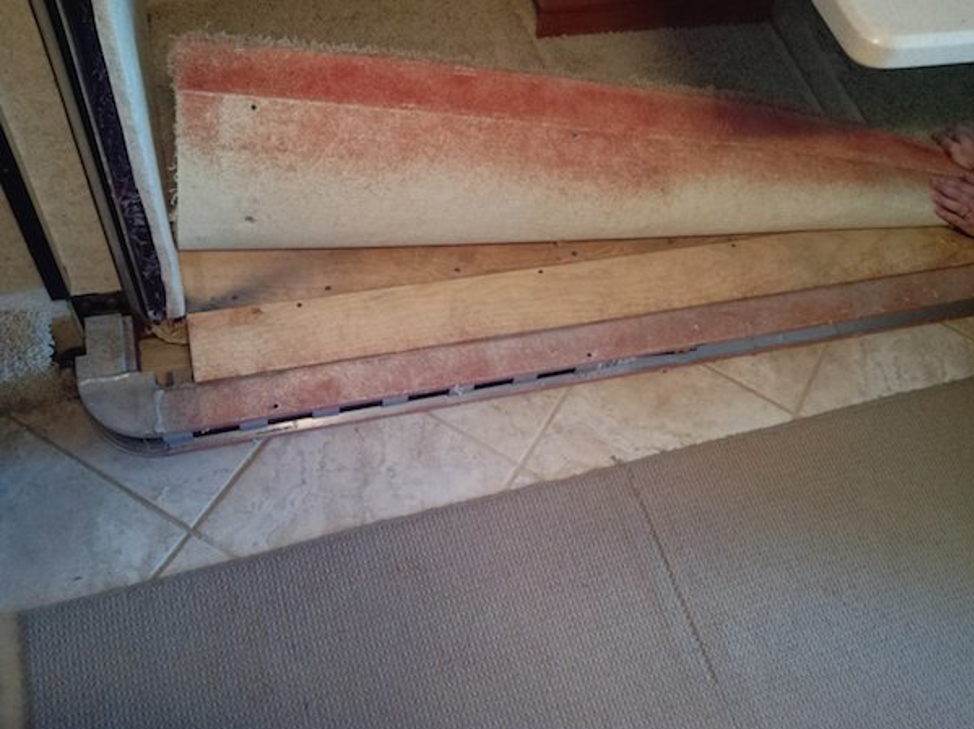
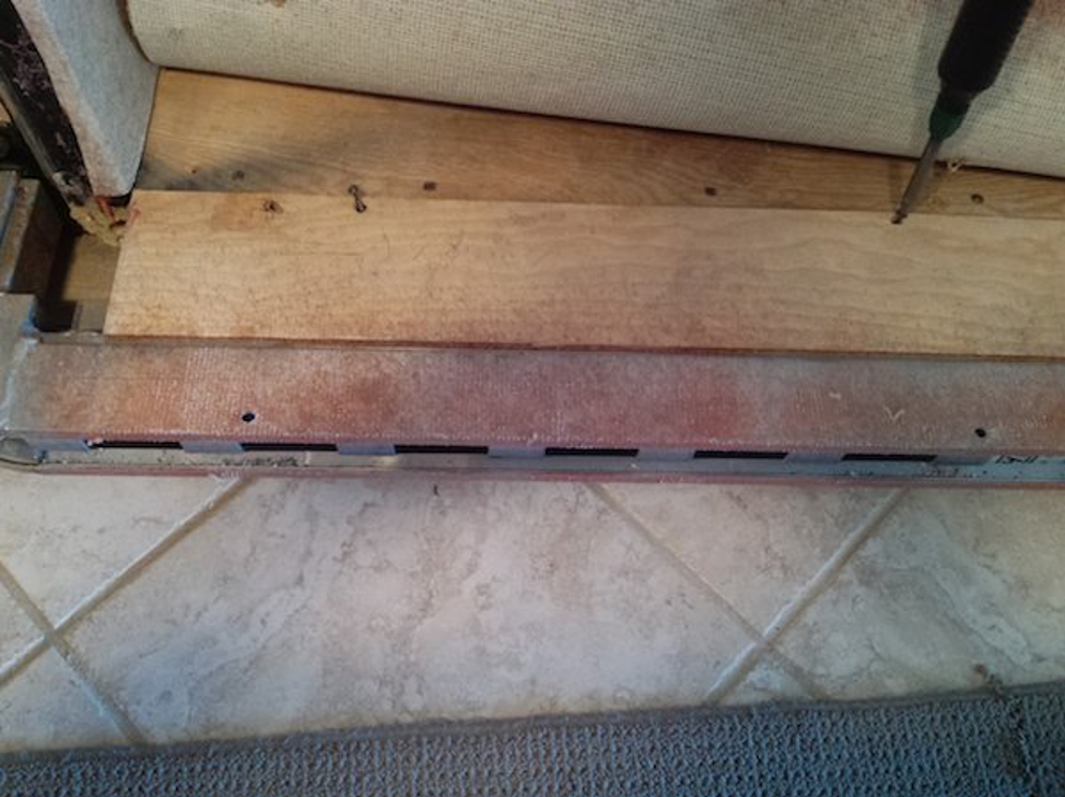
After lifting the carpet, you will see that there is a board that is about 3″ wide that runs the length of the aluminum slide channel. There were 4 screws across the rear. The front had a couple of beads of silicon, but the bead was easily broken by a little force. Once that board is removed, you will then see the aluminum channel which has 10 bolts holding it to the frame of the slide, just like the channel above you. The only difference is that the lower bolts are bolted DOWN and the upper bolts are bolted UP. I supported the frame with about 2″ of wood in an open spot. (per HWH instructions, the room should be supported…you can see the wood in picture #5). While there was initially no weight on it, I noticed later in the process that there was a bit of weight there. I learned that the slide may well tip in a little (about 3/4”) if you don’t have the room well supported. It actually did not turn out to be a problem.
Before removing those 10 bolts, you must take the outer nuts and star washers off of ALL FOUR cylinder rods, which will be in an extended position (as the room is retracted). Release the bladder so that the Extend button will work. Even tho the slide goes nowhere because all 4 rods are free, the electronics won’t let you do anything while the bladder is inflated.
When all 4 rods are retracted, you can remove the 10 bolts holding the channel and wiggle off the aluminum channel that you have unbolted. Pull it out about 2 inches and look to see that the two white rollers on the end of the cylinder have moved and are now lined up with the slots in the aluminum channel. When they are, you can pull the cylinder outwards from the channel and into the room.
After you swing the retracted cylinder into the room, bring the aluminum channel out a little towards the center of the coach. When the very last brass guides come out the back of the curve in the aluminum channel, the train mechanism and cylinder will come out of the aluminum channel easily.
At this point, release both of the solenoids under the coach to remove pressure (the Room extend and the room retract…not the lock solenoids). Then disconnect the two hydraulic lines and cap both of them on the cylinder and plug both of the lines. Very minimal fluid came out when I did this. I would recommend that you somehow mark which line is which. One goes to the “T” fitting and one goes to the 90-degree elbow. It looked possible to mix them up if you weren’t careful.
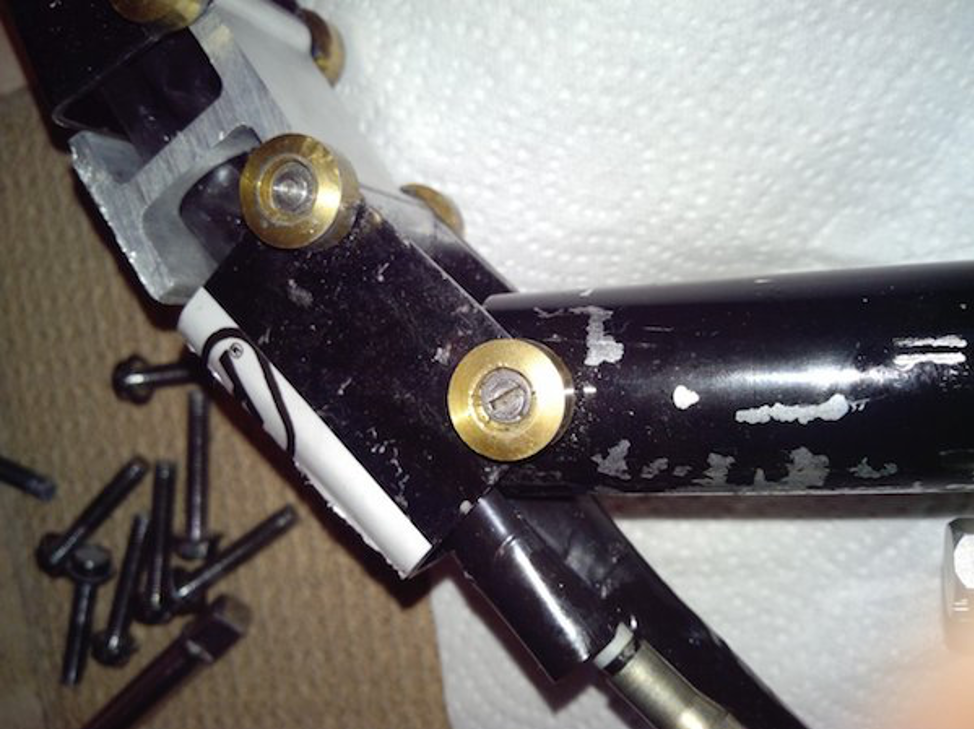
The train and cylinder connection is a single pin that is slotted. There are brass rollers on the top and bottom. They are held onto the shaft with Rotor Clip SHM-25 (or SHM-025) tamper-proof retaining rings. Line up the slot in the pin with the tiny opening of the snap-ring. After doing so, hold the screwdriver in the slot, slide it over so it is also holding the snap ring…maybe open a teensy bit. Then take a very tiny tool, like a little $1 store screwdriver, and pry the ring out and up from the other side of the slot (with your finger covering it so it won’t go flying).
Once the retaining ring is removed, simply push the pin down with your fingers and it will release the upper roller and the cylinder is now free.
One mistake I made was to open ALL of the lines on the cylinder, once I got it out. I was trying to get all the fluid out. Apparently, there is a spring inside and once the fluid was gone, the rod extended about half-way and wouldn’t stay back in. Just made for a longer package to send.
Pictures below are numbered in sequence. Once the cylinder is repaired or a replacement obtained, the re-installation is simply the reverse process of putting it back into the channel and bolting the channel back to the slide framing.
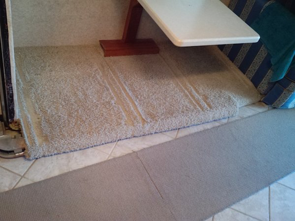
2. Lift up carpeting see wood covering bolts
3. Unscrew floor section
4. Channel Mounting bolts exposed
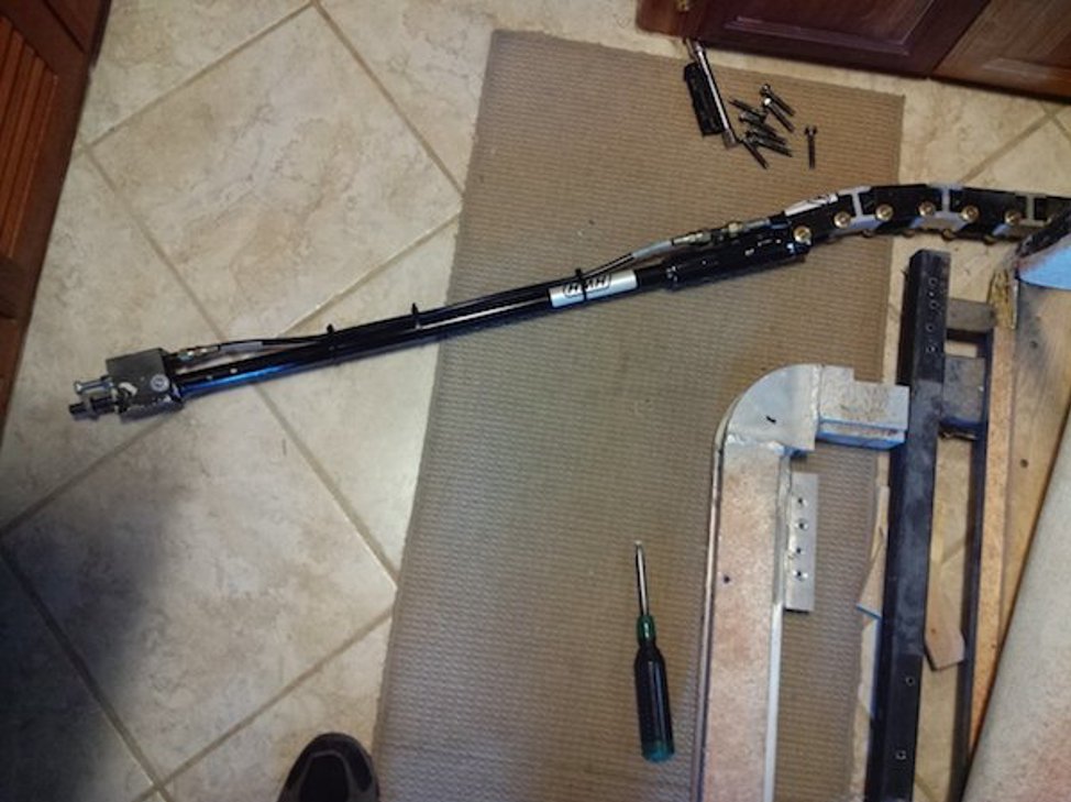
5. Train and cylinder removed from Channel
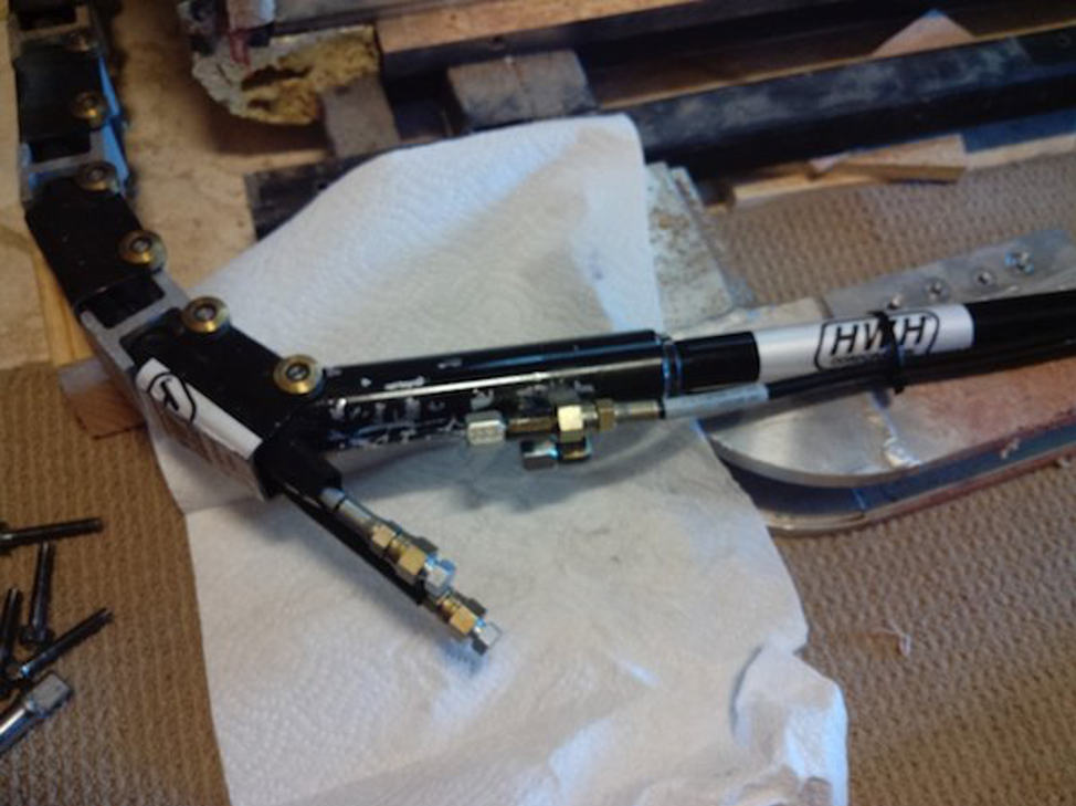
6. Hoses plugged and cylinder capped off
7. Cylinder still attached to the train
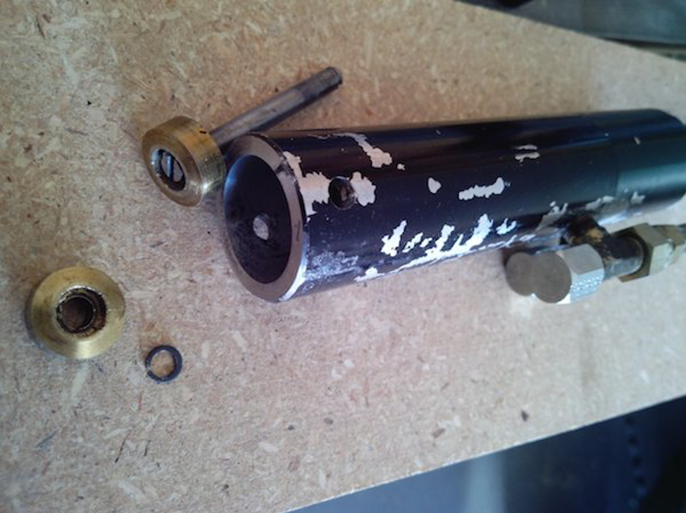
8. Mounting pin for cylinder
The Snap ring must be removed to separate the cylinder. Brad Recommends that you purchase the HWH tool to re-install the snap ring at reassembly. It is $10.00 and can likely be shipped with your repaired cylinder. There are two repair kits for Train parts. You shouldn’t need any of them for this repair. Only if you notice a physical problem with the train sections. RAP90883 is a link repair kit ($73.00) RAP90826 is a roller repair kit ($35.42). The links, altho scored on mine, don’t indicate that any replacement is necessary. Attached are documents showing the tool, the repair kits, and a drawing of what the snap ring looks like from a manufacturer’s website.
TRAIN DRIVE – ROOM EXTENSION ASSEMBLY SNAP RING REPLACEMENT TOOLS AND PROCEDURE
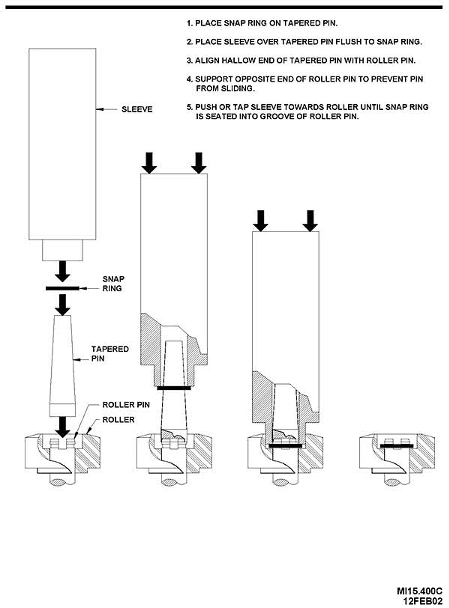
HWH snap ring tool mi15400c
Brad was successful in removing the Snap Ring without damaging it but will replace them with new ones. Manufacturer: Rotor Clip https://www.rotorclip.com/rotor-express.php – Various retailers use P/Ns – SHM-25, SHM-025, SHM-025SA. These rings may be purchased from https://www.huyett.com/Products/Fasteners/Retaining-Rings/Snap-Rings/SHM-025.aspx
New Cylinder/Rebuilt Cylinder Reinstallation
When the new cylinder gets back and is reinstalled, the system needs to be cycled several times to purge air and to get all 4 cylinders to “come into time” together. This cycling occurs while the 4 rods are NOT connected to the room, so care has to be taken to guide the threaded rod ends through the aluminum holes.
In my case, I shipped the cylinder off on 1/13, HWH got it 1/17 (Friday), replaced the end of the cylinder and had it back to UPS on 1/21. It got here 1/27, along with the handy little tool to put the snap ring on.
Snapring tool was most excellent. I used a rubber mallet on it, with a short 2 by 4 placed under the reinstalled pin holding the cylinder to the train. At first, my stroke was too gentle, and the ring did not seat on the pin. The second time, I gave it more and it worked well to get the ring onto the pin but was not fully seated in the groove, so I used the slide portion of the tool and gave it another tap. Easy. I did get my sample of 6 rings, so I used a new one.
You have to hold the cylinder (now attached to the train), and wiggle the aluminum channel so that the rollers go into it properly. Not too hard.
Once the rollers are set into the channel from the back, you swing the channel out a bit and swing the cylinder out even further (like straight out to the other wall…W/D cabinet in my case). This lets the base of the cylinder (opposite the rod end) start into the track. Now here is where I ran into an obstacle. The cylinder SHOULD just swivel/bend the train assembly and the end starts into the channel. I say start, as the other end (where the rod extends from) will only fit into the aluminum channel where two slots are cut into it…just wide enough for the cylinder’s white rollers to slide into their places. You will have to pull or push both the channel and the cylinder until they line up AFTER you get the base in the channel. That part is easy.
HOWEVER, my cylinder base absolutely would not start into the channel. There are 2 fittings…the T and the elbow…that were so wide that they simply would not enter it and I did not want to gouge up the threads. I even left the plastic caps on the openings, but it was the nut on the T fitting that was the upper problem and the threads on the lower elbow. I retrieved the old, damaged cylinder base and saw that it had been ever-so-narrower at this point of conflict. Maybe the old fittings were screwed a little further into the cylinder? But for whatever reason, I was required to file a wee bit of both the top and the bottom channel edges. Like 1/64″ depth and 1/2″ long on both top and bottom. I marked with a pencil where the conflict was and then got the cylinder out of my way to use a Dremel grinder and a little file. Once that was done, the cylinder went right in.
Next was to reinstall the channel with the 10 bolts. They are hard to get started properly, because when they were originally installed, Foretravel grinds off the bottom 1/8″ or so to make it smooth. Thus, the bolts must be carefully started in the soft aluminum, and then they will catch properly in the steel threads of the top and bottom of the frame tube.
BTW, a replacement cylinder is listed as $395. This one was rebuilt for .75 hr labor ($67.50) and $75.40 for the cylinder end module. When asked if I wanted it repainted for $15, I declined. They shipped the $10 snap ring tool with it as promised, so no extra freight for that part.
Follow the directions in ML23527 and close the two solenoid valves.
Re-synch
1. I had my wife touch the retract button briefly to make sure the new cylinder was properly hooked up..and the hoses weren’t backward. It shot out about 6″ (the right direction).
2. I now know why you are instructed to support the slide when the rods are unbolted. When the bladder is deflated, the upper part of the slide tilts in. This keeps the upper cylinder rods from fully extending through the holes to be locked back in place. I had a couple of blocks there, but I should have had them in place BEFORE I had released the rod ends. I had blocked it AFTER, but before taking the aluminum channel off. Apparently, it had already tilted a little. See #3.
3. Since the bottom generally does “lead” the top a bit, a total of 3 people worked out great for the task. My wife was at the button, and my friend Dave was at the forward, lower rod while I was at the rear lower rod. We had her hit the RETRACT button and we guided the extending rods through the lower assemblies. Then we went to the top ones which were still about an inch out. She pressed the RETRACT button again and we got them a little further, but still not synched together by the time it stopped moving. We repeated this process just a couple of times and everything finally came together. The top rods were not completely through the holes, yet the pump shut off and they were now in sync with each other. That is when we realized that the top of the slide was tilted in a bit (which elongates the train assembly and the rods are pulled back a bit. We gave the upper aluminum channels a bit of a shove, first the front, then the rear, and we got enough threads coming through to actually put the upper part of the slide in the right place by simply tightening the nuts on the rods. Then we put the nuts on the lower cylinders.
4. With a deep breath, I pressed the EXTEND button.
5. That slide has NEVER been so smooth and quiet as it glided itself into place. Back in and back out. Same result. Perfectly quiet and perfectly in synch. Ahhhh.
6. Two hours later, no creep. No creaking, no nothing. It just sits there doing what it is supposed to do: Staying in the fully extended position.
The total cost to get this problem properly tested