Steve Cook 2003 U320 40′
Over sudden dips in the road, the “Level System” light would flash momentarily along with a quick “ding” on the alarm. It took quite a few instances before it stayed lit long enough to see which warning was coming on. It seemed to get worse along the way as we bumped more (particularly on I-20 approaching the Metroplex). Pulling into our neighborhood, a rather tight right turn, it went off and “dinged” several times before shutting off.
We have had a temperamental “room in” slide sensor that’s been adjusted probably 4 or 5 times in total by MOT over the last year. We couldn’t force the alarm when pushing hard on the slide, though.
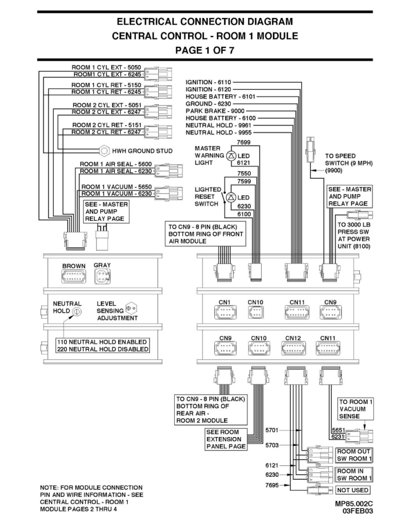
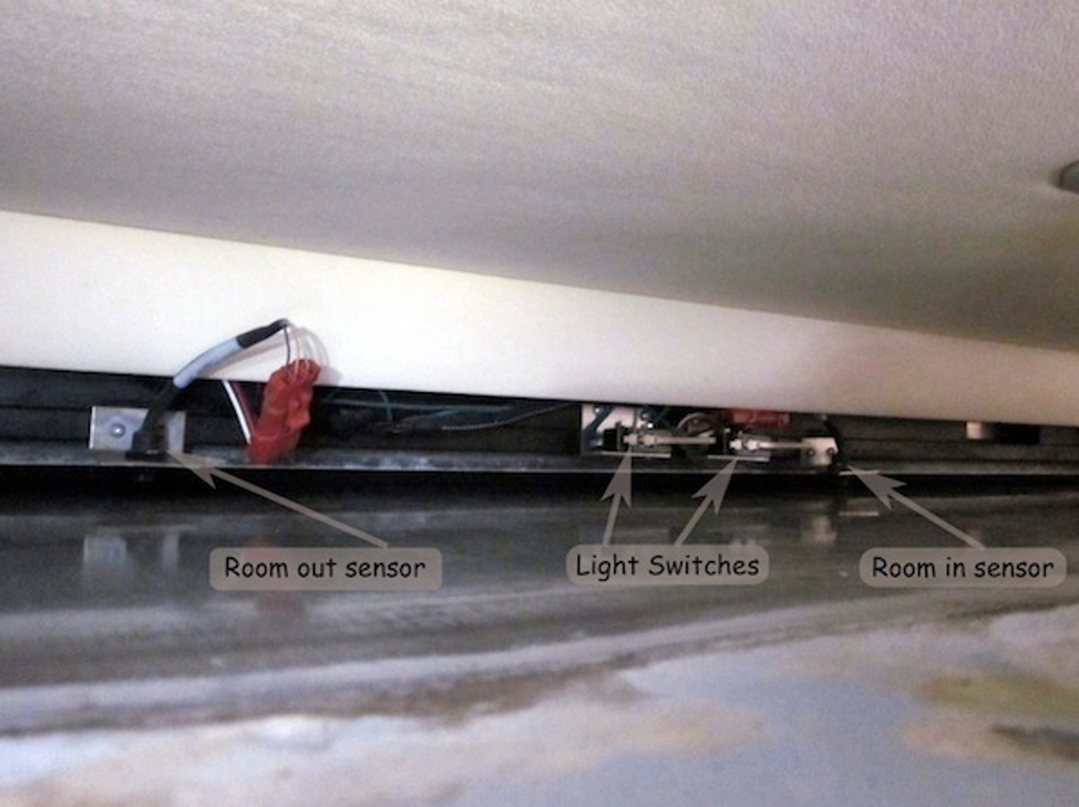
The switches are located behind the slide rooms large U shaped wrap-around valance. In ours, the switches are located in the center of the slide (you can see them if you peek in from the end of the slide), but to get to them you have to remove the valance. Generally, they have just adjusted the stop blocks to ensure the switches are depressed when the slide is closed. There are two mechanical switches and what looks like a reed switch on the right side. I need to open up the schematics tomorrow and see what I can learn as I’m not sure what all three do.
The two mechanical switches are for the room lights, just turns them off when the slide closes since they end up under the slide and as we know the original halogens are hot. The reed switch is the room in-out sensor, there is a magnet in the slide room that activates that switch. He said the gap in there should be about 3/16 of an inch or so and looking at the picture some new holes would have to be drilled in the bracket to move it down any further. You do have to take the top wood header off and extend the slide to get to the switch, so that’s today’s project.
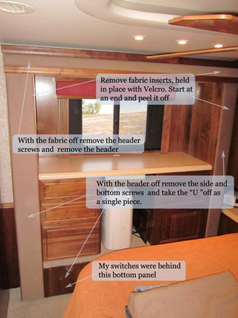
Finished adjusting all of the room sensors, don’t know if it fixed the problem until the next test drive. Here is what I did. To get to the sensors you need to remove the valance from the slide surround. In our FT the front slide had the switches on the top of the slide so you only had to remove the top part of the valance. The bedroom slide had the switches below the slide so you had to remove the top, sides, and bottom (I removed the top and then the sides and bottom as a unit) to get to them. Start!
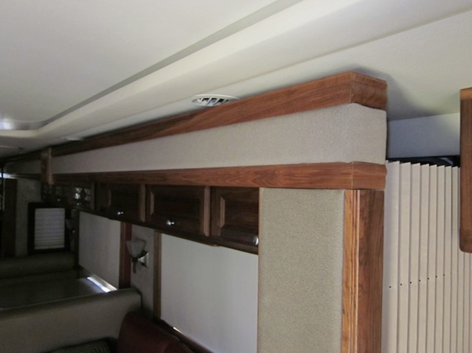
Remove the fabric, it’s attached to boards that are attached with Velcro to the slide valance. Just start at one end and slowly peel each section off.
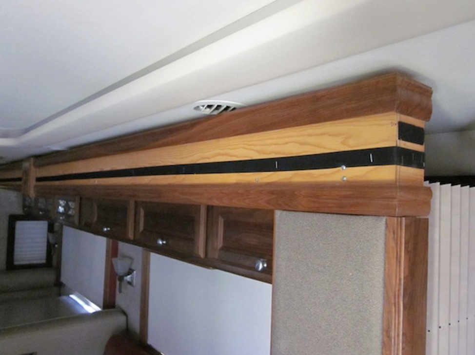
With that done you just remove the visible screws along the top, about a dozen or so, and then with a helper remove the long top valance, its length makes it awkward for one person to handle, plus its got some heft to it as well.
Once it’s removed you will be able to see and access the switches. In mine, there were 4 in all behind the valance, two magnetic reed switches for a room in/out status and two mechanical switches to turn off the ceiling halogen lights when the slide is in.
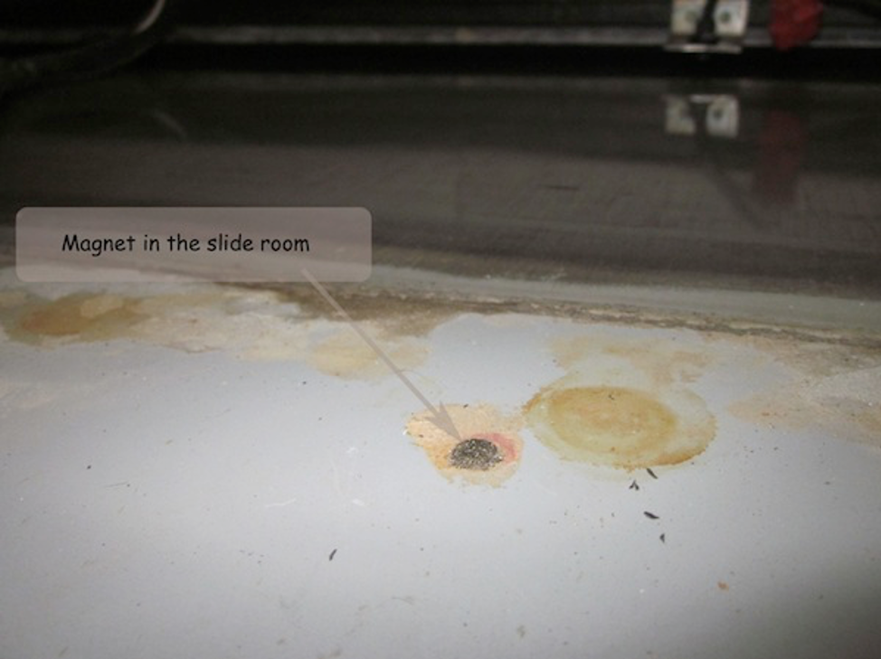
The switches interact with magnets that are embedded into the slide room, those magnets were still very strong so it would be the sensors that will need replacement at some point. I located the magnets using another small round magnet, I did that just to ensure the sensors were right over the magnets (they were)
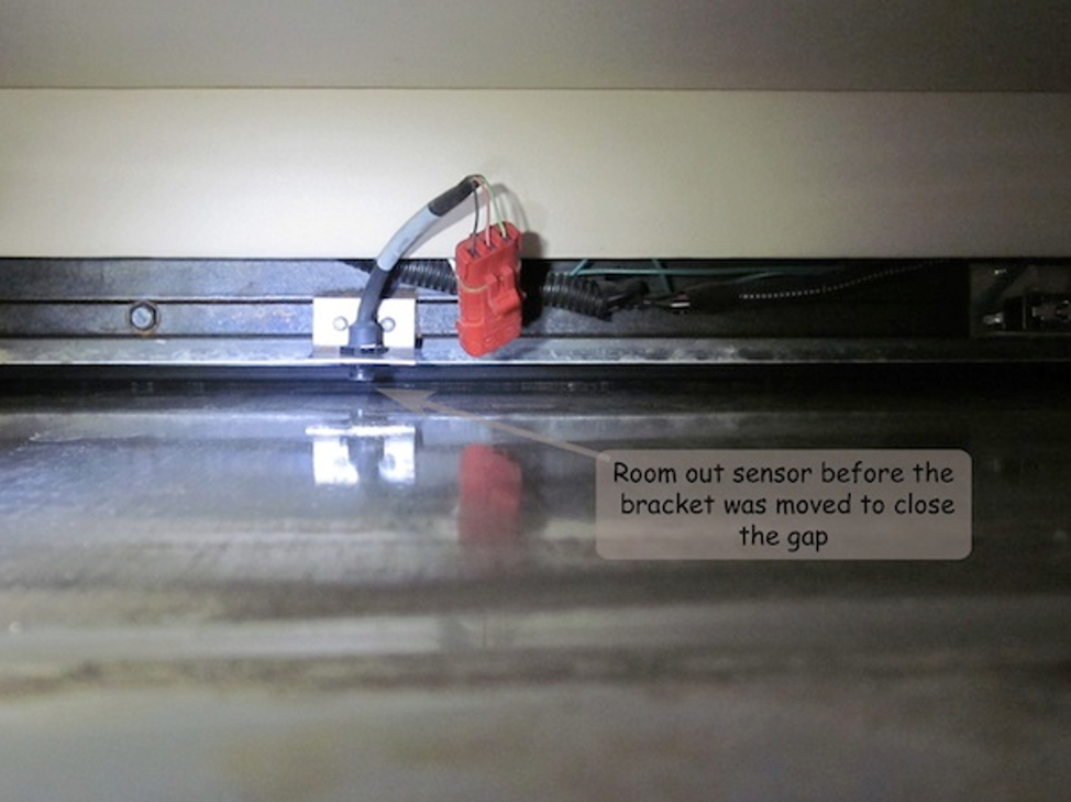
Here is the room out sensor before adjustment, the sensor has a short threaded area and was already set all the way down. I decided to add some new holes to the mounting brackets so I could shift them down closer to the slide. The brackets are made out of stainless so have a good drill bit. I noticed there were a couple of sets of mounting holes in the chassis frame, it looks like the brackets were lowered by drilling new holes in the frame once the build-in adjustment had been consumed.
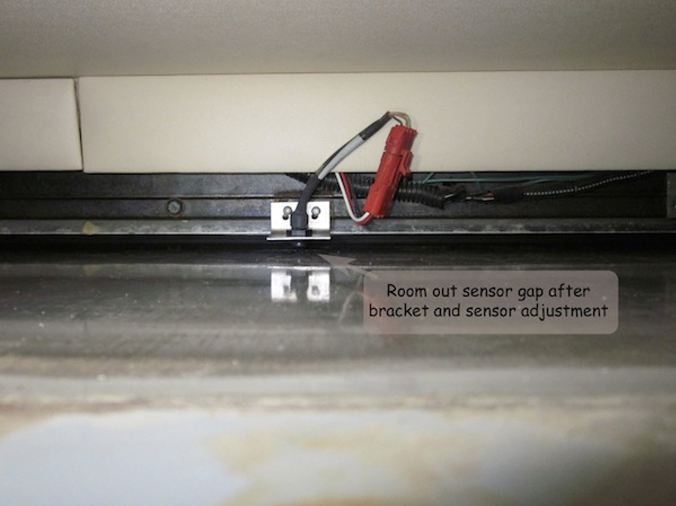
And here is what they looked like after I was done with my adjustments.
In our 2003 U320 coach the bedroom slide switches are located below the bottom panel, although our bedroom slide has a dresser/desk and not a wardrobe closet I think they are the same slide style (ie the synchronization cylinder etc is inside the coach and not in a bay below the slide like the large main room slide) To gain access you have to remove the top panel and then the remaining “U” as a single piece. One could remove the entire thing intact but I think it would be very awkward. I also released the left side curtain from the wall (Velcro again) as that is much easier to reattach then the retractor to its mounting clips which are on the “U” itself. I left the right side curtain attached and just pivoted the entire U section so I could get in to take a look. In mine, there was not a way to remove just the base without the verticals as the verticals were attached to the base and not the base to the verticals if that makes sense.
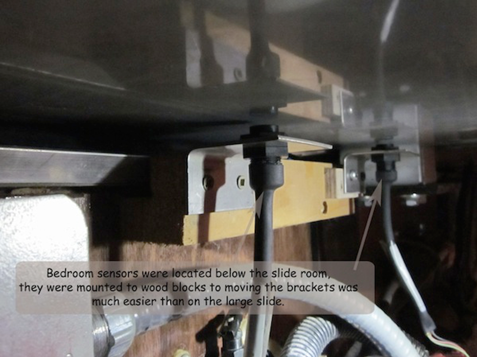
The bedroom ones were mounted to wood blocks to moving those brackets was a breeze, be sure to pre-drill those holes or you will split the wood.