1. PREFACE
In “Introduction to Air Suspensions” in our online technical school, the discussion was about what an air suspension is, how it works and some of the basic components of the air suspension. If you have not reviewed that section yet, it would be helpful to do so before continuing with this discussion. If you are confident you understand air suspensions, especially height control valves and pressure protection valves, please continue.
This section will deal with how the HWH hydraulic leveling systems interface with the air suspension. We will discuss several types of suspension air dumps. We will also discuss how the HWH air leveling systems interface with the air suspension to level the vehicle with the suspension airbags.
2. HYDRAULIC LEVELING AND AIR SUSPENSIONS
2-1 How air suspensions affect hydraulic leveling. Several factors combine to create issues when a vehicle with an air suspension is being leveled with a hydraulic leveling system. The two main factors are the compressibility of air and the transfer of weight through the suspension. As jacks lift a side or end of the vehicle, the suspension will usually shift weight to the other side or end of the vehicle. The added weight compresses the air in the suspension airbags causing that side of the vehicle to lower. This brings the suspension height control valves into play. They start to raise the side that is being forced down with added weight. This can defeat the action of the leveling jacks.
In other words, the air suspension fights the leveling system. As the jacks are trying to turn out the leveling lights, the air suspension in moving the opposite side or end, causing the leveling lights to possibly stay on longer than they should. The two sides most likely will seem to lift back and forth making the vehicle level at a much higher level than it should, if it can even achieve a level position.
More than likely, this will create a bigger problem with side to side leveling, because of the much shorter distance, than front to rear leveling. This problem is easily conquered. All you have to do is take the suspension airbags and height control valves out of the equation.
This is done by exhausting all of the air from the suspension airbags and disabling the height control valves. There are several ways to accomplish this. One way uses a normally closed set of valves supplied by HWH to dump the air from not only the airbags but also from the main air supply. The other way uses a pilot valve arrangement supplied by the chassis manufacturer to exhaust air from the airbags and isolate the height control valves from the airbags. We will discuss each method individually.
2-2 HWH air dump system. The HWH air dump system uses normally closed solenoid valves to dump the air from the vehicle suspension. The valves are teed into the air line that goes from the height control valves to the airbags. Usually, there will be one air dump valve for each height control valve. Depending on the suspension arrangement, sometimes it is possible to get by with two dump valves; one for the front suspension airbags and one for the rear suspension airbags. If installing a hydraulic leveling system on a vehicle with an air suspension, always contact HWH to obtain the proper air dump kit. The dump valves are controlled by the HWH leveling system controls. This type of system can be used with an automatic leveling system or a manually controlled leveling system; either touch panel or lever controlled.
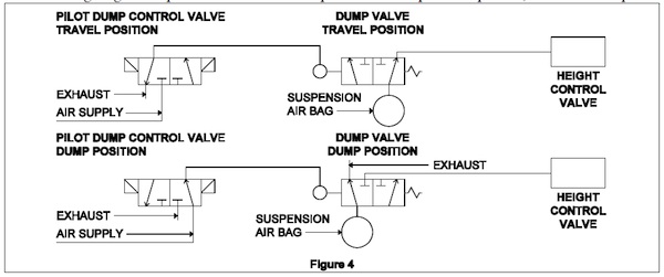
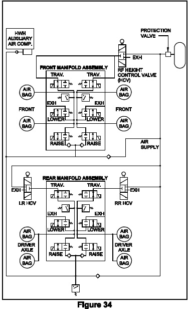
The following is a basic plumbing diagram for an HWH air dump system.
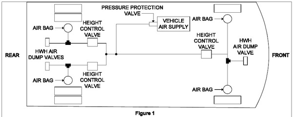
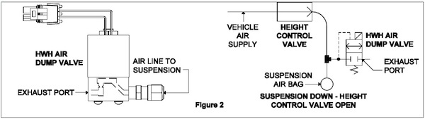
Again, note that the HWH air dump valves are plumbed into the system between the height control valves and the suspension airbags. Also, note that on this drawing I have included the vehicle air supply along with the pressure protection valve. Remember, as the vehicle lowers, the height control valve linkage opens the valve to allow air to flow from the vehicle air supply into the airbags. This does happen as the air is dumped from the airbags and the vehicle lowers. When the HWH air dump valves are opened, they not only dump air from the airbags but also (through the height control valves) from the vehicle air supply. One of the important rules to follow when using an HWH air dump system is the vehicle engine must be off. If the vehicle engine is allowed to run while dumping air and leveling the vehicle, the vehicle air supply will not dump properly. The vehicle engine air compressor will continue to fill the vehicle air supply. When the HWH air dump valves are closed, air from the vehicle air supply will be allowed to flow to the airbags if a height control valve is still in a down position after the leveling process is complete. If the system performs properly, at least one height control valve will probably be in the down position. Now the airbag for that height control valve will lift the vehicle back towards ride height. One or more jacks will not be on the ground. It will appear a jack has not extended properly or it retracted when it shouldn’t.
2-2.1 Valve information. The HWH valve is a simple, normally closed, electrically operated solenoid valve. The coil of the valve is a two-wire potted coil that is reversible. That means the coil should be watertight and the polarity of the coil wires does not matter, as long as one wire is + voltage and the other wire is ground. The + voltage side of the coil will always be the switched (control) side. The ground should be constant. The coil of the valve is a continuous duty coil and should open with 8 volts at the coil. The valve ports are labeled “1” and “2”. We use port 2 for the inlet air pressure and port 1 is the outlet or dumps side. Port 2 puts air pressure on the top side of the valve seat; this helps keep the valve closed.
2-2.2 Air dump operation. Except for the older 4 lever systems, the 400 series paddle switch systems, and 210/225 joystick systems, all HWH control panels will have a rocker switch or pushbutton for manual air dump control. The 210/225 systems have a harness that furnishes a wire for a rocker or toggle switch. A harness for the air dump valve connections is also supplied. HWH supplies a momentary toggle switch with a small air dump label. The installer can supply a different switch. It is recommended that this switch is a momentary switch with a continuous capability of 10 amps.
For most systems, to use the manual air dump button, the ignition must be on, the parking brake must be set and the control panel must be on. For the 625 single touch systems, the manual dump button will work with only the ignition on and park brake set. For all systems, the manual dump button is a momentary button and will have to be held on while dumping the air. When the button is pushed, the + voltage is turned on. The valve coil is energized and the valve seat is opened. The air will now be dumped from the air suspension. When the button is released, the + voltage is turned off and the valve seat closes. The air will stop dumping. With the air dump valves closed, the height control valves can cause the airbags to inflate, raising the vehicle back to ride height provided there is sufficient air pressure in the air supply.
As stated earlier, the air must be dumped from the vehicle suspension before the leveling procedure is started. For manual systems and automatic systems being operated manually, the dump button must be held until all air has exhausted from the airbags and suspension system. This means holding the dump button until you do not hear any more air escaping from the valves. You can also use the air pressure gauges to see when no more air is escaping. When the air pressure gauges stop moving, that should indicate leveling can begin.
Automatic systems will energize the air dump valves automatically before the leveling procedure is started. It is not necessary to manually dump the air. Systems with kick down style jacks will start the air dump when the on (HYD) button is pushed a third time. Non-single step systems will start the air dump when the on (HYD) button is pushed the second time. Single-step systems will start dumping air as soon as the LEVEL button is pushed. Air will dump from the suspension for approximately 20 seconds before the leveling process is started. The leveling process starts automatically after the 20-second delay. The system will keep the air dump valves energized throughout the leveling process and turn the valves off after the leveling process is completed and the system shuts off.
It is important to understand the pressure protection valve on the vehicle air supply. This valve maintains a specific amount of air pressure in the vehicle air supply for the vehicle air brake system in case of a problem with the vehicle air suspension system or other non-brake related air equipment. This is why after no more air is exhausting from the suspension air dump valves the vehicle air system pressure gauges will still show 65 to 70 psi air pressure in the system. All RV related vehicles that I have encountered have either two pressure gauges or one gauge with two needles. Depending on how the vehicle air tanks are plumbed into the system, both gauges or needles will drop to the 70 psi range or possibly just one gauge or needle will drop. In either case, when no more air is exhausting from the air dump valves, there should be approximately 65 or 70 psi remaining in the vehicle air system. This can create a problem for the leveling system.
The pressure protection valves are not required to be a “zero” leak valve. This may allow air to leak by the protection valve to the vehicle suspension. Over a period of time, depending on the size of the leak, height control valves in the down position will allow this air to flow to its airbag. This can lift the vehicle, raising one or more jacks off the ground. This can make it appear these jacks are retracting by themselves.
To check this, simply turn the leveling system controls on and push the manual “DUMP” button. If air starts to exhaust from the air dump valves, and the vehicle lowers, the protection valve is leaking. The problem is that because the protection valve is not a zero leak valve, there is no real repair for this unless the leak exceeds the allowable DOT tests. Even putting a new protection valve in the system will not guarantee a solution to the problem. Pumping the brake pedal to lower the air pressure in the vehicle air supply to approximately 30 psi is the only real solution. As long as there is not enough air pressure to actually raise the vehicle, a leaky protection valve will not affect the system.
Returning a vehicle to ride height is very simple; start the engine and build up some air pressure. The air dump valves should be closed unless the system is in an automatic leveling mode or the control panel is on and the dump button is being pushed. As the vehicle lowers when the jacks are retracted, the height control valves will be in the raised position. Air will be directed to the airbags until the vehicle is at the correct ride height.
WARNING: DO NOT CRAWL UNDER A VEHICLE UNLESS THE FRAME OF THE VEHICLE IS PROPERLY SUPPORTED. DO NOT USE THE AIR SUSPENSION OR LEVELING JACKS TO SUPPORT THE VEHICLE WHILE UNDER THE VEHICLE.
2-2.3 HWH air dump valve diagnostics. The diagnostics for the air dump valves are also very simple.
If the valves will not dump air, first determine if one or all valves will not dump air. If no valves will dump air, the control box or panel would probably be the best place to start. If anyone valve is working, that indicates the control box or panel is working. (The 4 lever 100/110 systems have two separate outputs for the front and rear valves. Although unlikely, if the front or rear valves are working and the others are not, it could be the control panel.) In either case, starting at the dump valves should always get you to the problem. First, check the exhaust ports of the valves for blockage; these ports can become clogged with dirt or small bug homes. If the ports are not plugged, check for voltage between the two wires for the valve. You need at least 9 volts (with the valve plugged in and turned on) to open a dump valve. If good voltage is present, the dump valve is bad. If voltage is not present, work your way back to the control box or panel to determine where the problem lies.
If the vehicle will not return to ride height, check to see if the air is exhausting from the dump valves. If no air is exhausting from the dump valves, the problem is with the vehicle suspension, probably the height control valves. If the air is exhausting from a dump valve, unplug the valve. If the valve continues to exhaust air, the valve is the problem. If the valve closes when unplugged, the harness wires are shorted to + voltage or the controls are bad.
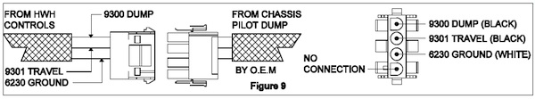
2-3 Pilot air dump systems. The valves and other equipment for a pilot air dump system are provided by the vehicle or chassis manufacturer. This type of system can be controlled mechanically or electrically. Electric controls can be provided by the vehicle manufacturer or can be part of the HWH leveling system.
The diagram represents a typical pilot air dump system. It is important to understand that this equipment IS NOT supplied by HWH. This equipment is supplied and installed by the vehicle or chassis manufacturer. It is important for you to contact the manufacturer before diagnosing or attempting to repair a pilot air dump system. For a detailed review and explanation of the pilot air dump equipment, refer to the vehicle or chassis manufacturer.
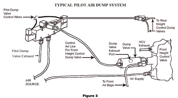
An advantage of using a pilot dump system is that the dump valve isolates the airbag from the height control valve while dumping the air from the airbags. Air is not dumped from the main air supply and the vehicle engine can be run during a leveling procedure. Another advantage is the pilot dump valve stays in the position it is shifted to. This means there should be no problem with air seeping into the airbags after the leveling procedure is finished. BUT, this can also be a disadvantage if there is a system failure. If a failure causes the pilot valve to not shift into the travel position, the vehicle cannot return to ride height.
2-3.1 Pilot air dump equipment. The pilot air dump system consists of a pilot control valve and a dump valve at each height control valve along with the necessary plumbing and wiring. The electrically operated pilot control valve has an electric coil on each side of the valve. Switched + voltage is used to energize these coils. When a coil is energized, the pilot valve is shifted to the travel or dump position. In the travel position, the pilot control valve connects the individual dump valves to an exhaust port. This allows the dump valves to shift to the travel position, allowing the height control valves to control the air in the airbags. In the dump position, the pilot control valves use air pressure to shift the individual dump valves to the dump position. In the dump position, the height control valves are isolated from the airbags and the air is exhausted from the airbags.
Note: Air pressure is required to shift the pilot control valve from one position to another. If the system air pressure is low, the valve may not shift until adequate air pressure is built up in the system with the engine air compressor.
2-3.2 HWH pilot dump controls are part of the system control box or control panel. There will be a + voltage output for dump and travel. With a touch panel controlled system, each output will be fused. With a 200 series joystick leveling system, both outputs are protected with the main panel fuse. HWH supplies a harness to connect to the pilot control valve. This harness has three wires in it and terminates into a 4 pin UML connector. The three wires are a black wire labeled 9300 for the dump signal, a black wire labeled 9301 for the travel signal and white wire for ground. One endpin has no wire, the next wire is the white ground wire, the next wire is the black 9301 travel wire and the other endpin is the black 9300 dump wire. Refer to system electrical connection diagrams for specific control box or panel connections, fuse locations and led information where applicable.
2-3.3 Pilot dump operation. Each different type of control system operates the pilot dump system a little differently. One thing that is consistent between all of the systems is that the ignition must be on and the parking brake must be set for the pilot dump system to dump the air. Another consistent feature is when the ignition is on and the parking brake is off, there is a + voltage signal to the travel side of the pilot control valve.
There are several types of pilot dump controls for past or present, manual and automatic systems.
1.) There is a rocker switch panel that can be used with or without any leveling system. The panel only has a fuse and a rocker switch. With the ignition on and the park brake set, push the rocker to “AIR DUMP”. This will shift the pilot control valve to the dump position and the air will dump from the airbags. With the ignition on, push the rocker switch to “TRAVEL”. This will shift the pilot control valve to the travel position. The airbags should start to fill and the vehicle should return to ride height. If the ignition is on and the parking brake is released, the pilot control valve will shift to the travel position.
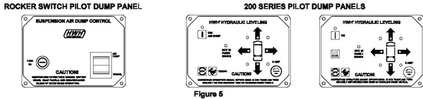
2.) The light panels for the 200 series joystick systems can operate pilot air dump systems. There are two different 200 series panels. (Shown on the previous page.) One has a “DUMP” button and one does not. Winnebago used the panel without the “DUMP” button. With either panel, the ignition must be on and the parking brake must be set to dump the air. The panel without a “DUMP” button will shift the pilot control valve to the dump position when the “ON” button is pushed. The signal to the pilot control valve is constant until the “OFF” button is pushed or the ignition is turned off. On the panel with the “DUMP” button, the “DUMP” button must be pushed to shift the pilot control valve. The “DUMP” button is momentary but the signal to the pilot control valve will be constant after the “DUMP” button is released. These panels have a button with a symbol that looks like a rabbit. This is the travel button. With the ignition on, push the rabbit button. The pilot control valve will shift to the travel position. The airbags should start to fill and the vehicle should start to return to ride height. The travel signal will be constant after the rabbit button is pushed and released. If the ignition is on and the parking brake is released, the pilot control valve will be shifted to the travel position. The travel signal is constant with the park brake off and the ignition on.
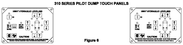
3.) 310 series touch panel systems have two different panels, with and without a “DUMP” button. The panel without a “DUMP” button was mainly used by Winnebago. This panel would send a +12 volt signal to shift the pilot dump control valve to the dump position when the “ON” (I) button was pushed. The ignition switch must be in the “ON” position and the parking brake must be set for the system to send a dump signal. The dump signal is present only while the “ON” button is being pushed. The panel with a “DUMP” button must have the ignition on, the park brake set and the panel must be on for the “DUMP” button to work. When the “DUMP” button is pushed, the panel will send a +12 signal to shift the pilot dump control valve to the dump position. The +12 signal is only present while the “DUMP” button is being pushed. Both panels have a button with a symbol that looks like a rabbit. This is the travel button. This button works with the panel off or on, the parking brake set or off but the ignition must be on. The travel signal is a +12 signal and is only on while the travel button is being pushed. If the ignition is on and the parking brake is off, the travel signal will be constant.
4.) 305/325 shortboard touch panel systems all use the same touch panel; systems with pilot air dump, HWH air dump valves or no air dump. No 305/325 panels have a “DUMP” button. The ignition must be on (or an accessory) and the parking brake must be set to dump air. When the “LEVEL” (I) button is pushed, the panel sends a ground signal to the control box. The dump relay is turned on and a +12 signal is sent to shift the pilot dump control valve to the dump position. The signal is constant until the “OFF” button is pushed or the ignition is turned off. The ignition must be on to shift the pilot control valve to the travel position. The panel must be off. Pushing “STORE” signals the control box to send a +12 signal to the pilot control valve to shift to the travel position. The signal is constant. If the ignition is on and the parking brake is off, there is a constant +12 travel signal to the pilot control valve.
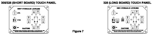
5.) 325 longboard touch panel system. This is a manual touch panel system. The touch panel has a “DUMP” button and is the same panel for either the pilot dump system or the HWH dump valve system. The ignition must be on (or an accessory), the parking brake must be set and the touch panel must be on for the “DUMP” button to work. When the “DUMP” button is pushed, the control box turns the travel relay and the dump relay on. The travel relay is a normally closed relay so when the dump button is pushed, the travel relay contacts open and the dump relay contacts close. This supplies a + voltage signal to the pilot control valve to shift the valve to the dump position. The signal is constant until the “OFF” button is pushed or the ignition is turned off. After the “DUMP” button has been pushed, any time the ignition is turned on, the control box will pulse the dump relay on to make sure the pilot control valve stays in the dump position.
To return the pilot control valve to the travel position, the ignition must be on. If the parking brake is on, pushing the “STORE” button will turn off the travel relay. When the travel relay is off, the normally closed contacts of the travel relay direct + voltage to the pilot control valve. The pilot valve shifts to the travel position. The travel signal is then constant any time the ignition is on. If the ignition is on and the parking brake is released, the travel relay is turned off and a constant + voltage signal is directed to the pilot control valve.
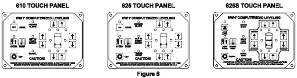
6.) 610 central ground automatic leveling system. The ignition switch must be on, the parking brake must be set and the touch panel must be on to shift the pilot control valve to the dump position. Pushing the “DUMP” button sends a + voltage signal to the pilot control valve. This shifts the valve to the dump position. The dump signal will only be present when the “DUMP” button is being pushed. Also in the automatic mode, the leveling system sends a + voltage dump signal to the pilot control valve. When the “ON” (HYD) button is pushed to start the actual leveling process, a + voltage dump signal is sent to the pilot control valve to shift the valve to the dump position. There is a delay of approximately 20 seconds after the dump signal is sent before the leveling process is started. The dump signal is constant until the automatic leveling process is finished and the touch panel shuts off. The ignition must be on to shift the pilot control valve to the travel position. If the parking brake is set, the “STORE” button must be used to shift the pilot valve to the travel position. The touch panel must be on. The travel signal will be constant while the STORE indicator light is on. Any time the ignition is on and the parking brake is released, there will be a constant + voltage travel signal to the pilot control valve.
7.) 625 automatic leveling system. The touch panel has a “DUMP” button and is the same panel for either the pilot dump system or the HWH dump valve system. The ignition must be on (or an accessory), the parking brake must be set and the touch panel must be on for the “DUMP” button to work. When the “DUMP” button is pushed, the control box turns the travel relay and the dump relay on. The travel relay is a normally closed relay so when the dump button is pushed, the travel relay contacts open and the dump relay contacts close. This supplies a + voltage signal to the pilot control valve to shift the valve to the dump position. The signal is constant until the “OFF” button is pushed or the ignition is turned off.
For automatic leveling, when the “ON” (HYD) button is pushed to start the actual leveling process, the travel relay and the dump relay is turned on. This supplies a + voltage signal to the pilot control valve to shift it into the dump position. The dump signal is constant until the touch panel turns off or the ignition is turned off. After the “DUMP” button has been pushed or the automatic leveling function is used, any time the ignition is turned on, the control box will pulse the dump relay on to make sure the pilot control valve stays in the dump position. To return the pilot control valve to the travel position, the ignition must be on. If the parking brake is on, pushing the “STORE” button will turn off the travel relay. When the travel relay is off, the normally closed contacts of the travel relay direct + voltage to the pilot control valve. The pilot valve shifts to the travel position. The travel signal is then constant any time the ignition is on. If the ignition is on and the parking brake is released, the travel relay is turned off and a constant + voltage signal is directed to the pilot control valve.
8.) 625S single step automatic leveling system. The touch panel has a “DUMP” button and is the same panel for either the pilot dump system or the HWH dump valve system. The ignition must be on (or an accessory) and the parking brake must be set for the “DUMP” button to work. When the “DUMP” button is pushed, the control box turns the travel relay and the dump relay on. The travel relay is a normally closed relay so when the dump button is pushed, the travel relay contacts open and the dump relay contacts close. This supplies a + voltage signal to the pilot control valve to shift the valve to the dump position. The signal is constant until the “EMERGENCY STOP/CANCEL” button is pushed or the ignition is turned off.
For automatic leveling, when the “LEVEL” button is pushed to start the actual leveling process, the travel relay and the dump relay is turned on. This supplies a + voltage signal to the pilot control valve to shift it into the dump position. The dump signal is constant until the leveling and stabilizing process is complete or the ignition is turned off. After the “DUMP” button has been pushed or the automatic leveling function is used, any time the ignition is turned on, the control box will pulse the dump relay on to make sure the pilot control valve stays in the dump position. To return the pilot control valve to the travel position, the ignition must be on. If the parking brake is on, pushing the “STORE” button will turn off the travel relay. When the travel relay is off, the normally closed contacts of the travel relay direct + voltage to the pilot control valve. The pilot valve shifts to the travel position. The travel signal is then constant any time the ignition is on. If the ignition is on and the parking brake is released, the travel relay is turned off and a constant + voltage signal is directed to the pilot control valve.
2-3.4 PILOT DUMP DIAGNOSTICS. For HWH, pilot dump diagnostics consist of testing for a + voltage signal to shift the pilot control valve to the dump or travel position. All HWH systems that control the pilot dump have a straight 4-pin UML connector with three wires that connect to a harness supplied by the vehicle manufacturer. There are two black wires (9300 – Dump & 9301 – Travel) and one white wire for ground. The hardest part of diagnosing a pilot dump issue will be determining which HWH system is being used and where to locate the 4-pin plug. Contact HWH Corporation for assistance with either issue. Refer to the above information to determine when there will be a signal for dump and travel.
Check the appropriate fuse. If the fuse is ok, then check for + voltage between the appropriate black wire (9300 – Dump & 9301 – Travel) and the white ground wire. If voltage is present, the issue is with the pilot dump equipment and you should contact the vehicle or chassis manufacturer. If voltage is not present, check for voltage on the correct output pin. If voltage is present, there is a problem with the harness wires or connections. If voltage is not present, the problem is most likely the control box or panel. If the fuse is blown, unplug the 4-pin UML connector and replace the fuse. If the fuse now blows, there is a short in the harness or control box/panel. If the fuse does not blow with the harness unplugged, the problem is with the vehicle pilot dump wiring or equipment. Contact the vehicle or chassis manufacturer.
HWH AIR LEVELING SYSTEM EXPLAINED
HWH AIR LEVELING
This discussion will cover the basic HWH air leveling systems. This section will not cover the HWH Active Air system. The Active Air system will be discussed as an individual subject in the HWH online technical school.
3-1 What is air leveling? Very simply, air leveling uses the vehicle’s air suspension to level the vehicle. HWH isolates the suspension airbags from the heights control valves. This way HWH can control the airbags for leveling. To level the vehicle, the air is released from the suspension airbags to lower the vehicle or added to the suspension airbags to raise the vehicle. This is done using the HWH Bi-Axis® leveling principle.
Bi-Axis® leveling. Bi-Axis is working with two corners of the vehicle at a time to level the vehicle side to side and then front to rear. If the left side is low, the right rear and right front corners are raised to level the vehicle side to side. If the front is low, both front corners of the vehicle are raised to level the vehicle. With a motorized vehicle, you always level the vehicle (if needed) side to side before leveling front to rear.
All present-day air leveling systems incorporate the Bi-Axis four-point leveling principle, but the original 500 series air leveling system and some early 600 series air leveling systems were three-point leveling systems. That means the two rear corners were controlled independently but the two front corners were controlled together. With a four-point system, there is a raise, lower and travel valve for each corner of the vehicle. With a three-point system, there is only one raise, lower and travel valve for both front corners. This will be explained in greater detail later in the HWH Air Leveling section of this lesson.
The majority of air leveling systems are installed by the vehicle manufacturer but air leveling can be installed on any vehicle with a full air suspension that incorporates height control valves. This is not a normal aftermarket installation but an air leveling system can be installed on an existing vehicle with the approval of HWH Corporation. The installer must be approved by HWH Corporation.
Air leveling systems can also be combined with the HWH hydraulic leveling systems. This system uses one control box and a touch panel. Vehicles equipped with a combination air or hydraulic system gives the operator the choice of using either the air leveling system or the hydraulic leveling system. If one system has been used to level the vehicle, do not use the other system. Example: If the hydraulic system was used to level the vehicle, do not use the air leveling system unless the hydraulic system has been retracted.
3-2 Components of a basic air leveling system.
(This does not include the HWH Active Air system)
The main components of an air leveling system are the control box, touch panel, air solenoid valve manifolds, and an auxiliary air compressor. The older systems have a remotely mounted level sensing unit. There are also the wiring harnesses that are normally supplied by HWH although a few manufacturers may supply some of the harnesses. Plumbing equipment such as air lines or fittings other than those supplied with the HWH air manifolds and air compressors are supplied by the installer.
3-2.1 Control boxes. The control box processes information received from the touch panel, level sensing unit and pressure switches to control system indicator lights and the leveling equipment. Although a few manual control air leveling systems were produced in the mid-1990s, most of those were upgraded to automatic leveling system and all present-day air leveling systems are computerized automatic leveling systems. All control boxes will have a computer chip with a 4 or 5 digit number on it. The number may also have a – number. Example: A9636-5 The A may not be present. The number and the – number are what are needed to identify a program. You may be asked to provide this number if specific programming information is needed when diagnosing air leveling issues.
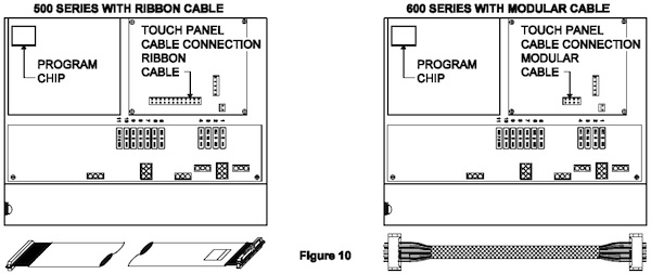
There have been several different style control boxes for air leveling. The original air leveling system was the 500 series system. This system used a 9” X 14” aluminum control box. The next generation was the 600 series system. This control box looked exactly like the 500 series. The difference between the two systems was the touch panel cable. The 500 series system used a 2” wide flat ribbon touch panel cable. The 600 series system used a ½” wide modular touch panel cable. Both systems remained in use until about 2002. The 500 series control box is still used for Prevost buses that use HWH air leveling.
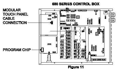
The 680 series system was a bridge system to the 2000 series CAN system that is in use today. The 680 series control box was 14” x 18” aluminum box. Instead of plugs in the box, most of the connections to the box were made to connectors on short pigtails coming from the box. This box was only used if the vehicle had HWH room mechanisms with HWH room locks and air seals. The air leveling side of this type of control box was like the 600 series leveling system. In fact, the same two computer pc boards used in the 600 boxes are used in the 680 boxes. The program number used is different and the output boards use relays instead of transistors. A modular touch panel cable is used.
The 2000 series CAN system is the system that is presently used for all air leveling systems except those used for Prevost busses. The Active Air system is a CAN system with a different type of system control. CAN stands for Controller Area Network. The CAN system has a central control module with a “mother” board along with input and output modules that the central control module controls. A simple CAN system will only have only two modules or boxes; a central control/output box and a touch panel. In a CAN system, the touch panel is considered a module. A complex CAN system can have an almost unlimited amount of control boxes or modules. Except for one or two possible exceptions, all air leveling only CAN systems will have only the two modules; the control box and the touch panel.
3-2.2 Touch panels. There are several different styles of touch panels for air leveling systems. It is important to get the correct part number when replacing a touch panel. A replacement panel with the same Lexan (touch panel decal) and cable connector may not be compatible with the existing panel. Some touch panels may have a small sticker on the back with the panel part number. Some will have the part number written on the pc board with a felt pen. If no part number is available, get the part number off the control box. With the control box number, the correct touch panel part number can be determined by HWH. The following panels are examples of what is available. When part numbers are not available, contact HWH Corporation technical assistance.
Do not order a touch panel unless you are positive of the correct part number.
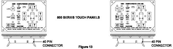
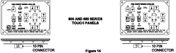
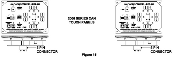
The touch panels shown in this section represent the most common styles used. There are other touch panels for air leveling systems that are not shown. Always use the correct touch panel for replacement. With the 2000 series CAN system panels, some panels have a terminating resistor and others do not. These panels are not interchangeable even though they appear to be the same. Some touch panels also have different programming.
Always make sure the correct replacement panel is ordered. Contact HWH Corporation for assistance if necessary.
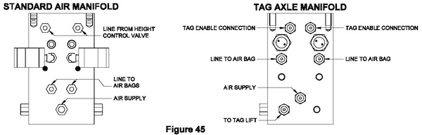
3-2.3 Air solenoid valve manifolds. Most air manifolds have three basic functions:
1.) Allow air to pass through the manifold to or from the height control valves to control the suspension airbags for traveling.
2.) Direct air to the suspension airbags to raise the vehicle for leveling and other functions.
3.) Exhaust air from the suspension airbags to lower the vehicle for leveling and other functions. Some tag axle air manifolds have valves that control a tag lift mechanism. Another tag axle manifold controls the air for traveling and the tag lift mechanism only.
Like control boxes and touch panels, there are a lot of different air manifolds. Some manifolds have different plumbing arrangements or types of air line fittings. Some manifolds have one, two or three pressure switches, some have no pressure switches.
It is important to note that although there is one main valve used on-air manifolds, a few manifolds will use a different valve with larger orifices.
This valve is visually the same unless comparing the orifice size.
The basic air manifold has a left side and a right side. Each side has three valves that do the same thing.
1.) The traveling valve is used to isolate the airbags from the height control valves. When traveling, this valve is open to allow the height control valves to function. When leveling, the travel valves are closed, this isolates the airbags from the height control valves.
2.) The raise valve is used to direct air into the airbags. This raises the vehicle.
3.) The lower valve is used to exhaust air from the airbags. This lowers the vehicle.
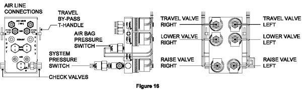
The drawing below is an air manifold for the drive axle of a vehicle. It is labeled as a present-day manifold. Either side of the manifold can be right or left but HWH now labels left and right on the manifolds. It is important to pay attention to the labeling because the valves are prewired with a short pigtail. The right and left side air lines must be plumbed into the right and left side valves. On older manifolds that are not labeled, you must maintain the proper wiring and plumbing connections.
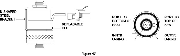
3-2.3.1 The air solenoid valves are normally closed valves operated with a + 12 volt, continuous duty coil. The + voltage to the valve coil is always the switched (control) side of the coil. The valve is required to open with 8 volts. If there are less than 8 volts, the valve may not function. The valve is a screw-on valve with two o-rings, an inner o-ring, and an outer o-ring. The o-rings should be lightly lubricated before the valve is installed.
Valve diagnostics. Check the voltage between the two wires for the coil. The valve needs to be plugged in and turned on. If there are at least 8 volts to the coil, the valve should open, allow air to flow. If the valve will open it is ok. If the valve will not open, replacing the coil will probably fix the valve. If the coil of the valve is bad, the coil itself can be replaced. If replacing the coil, the u-shaped steel bracket must be retained. If there are less than 8 volts or 0 volts to the coil, the diagnostics must move to the system controls or harness.
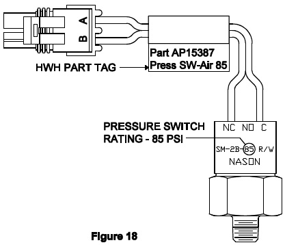
3-2.3.2 Air pressure switches. Pressure switches are used to monitor airbag pressure or system pressure. The first air leveling systems will have no manifold pressure switches. Air pressure switches were not incorporated into the systems until the early to mid-1990s. The first air leveling systems with pressure switches will have 4 airbag pressure switches, one for each corner of the suspension, with no system pressure switch. These pressure switches were only used as low airbag pressure warning switches. As the air leveling systems evolved, a system pressure switch was added and the airbag switches were also used during the leveling procedure. There have been different styles and pressure ratings for these switches.
The different air pressure switches are discussed in detail in Lesson 9 “Electronics and HWH” in the online technical school. The most common airbag switch is a 20 psi switch. 10 psi and 35 psi switches have been used. The most common system pressure switch is an 85 psi switch. A 100 psi system pressure switch has been used. The pressure switch rating is commonly included in the part number that is on the switch itself and is also included on the part number tag added by HWH.
The air manifold pressure switches have normally closed contacts and open when the pressure switch rating is reached. Example: From 0 to 20 psi, the contacts of a 20 psi airbag switch are closed. When the pressure in the airbag reaches 20 psi, the switch contacts open. The air manifold pressure switches switch a ground signal to provide information to the control box.
The system pressure switch is used as a low air pressure warning switch only. It monitors the air pressure that is in the suspension system after the pressure protection valve.
The airbag pressure switches are used as airbag low air pressure warning switches when the system is in the travel mode. When the system is in the leveling mode, the airbag pressure switches are used to protect the vehicle from excessive twisting during the leveling procedure, specifically when the system is doing a lower procedure. The program for this has changed several times and a specific chip number may be needed to describe the program used by the existing control box. The airbag pressure switch program that is in use at the time this is being written is as follows:
Automatic leveling-pressure switch program. When the system is performing a front (or rear) lower procedure and either front (or rear) pressure switch comes on, low air pressure in an airbag, the lower procedure will halt. The system will immediately go into a raise procedure for the opposite end to try to achieve a level position. The system will not return to a lower procedure during the present leveling sequence. The system will use a lower procedure if re-leveling the vehicle in the sleep mode. The system still monitors the airbag pressure switches and will inhibit a front or rear lowering procedure if an airbag pressure switch comes on.
Manual leveling-pressure switch program. If either front airbag pressure switch is on, the system cannot perform a front lower procedure, the front down arrow (lower) button will not function. Both sides down arrow buttons will still function and the rear down arrow button will function. Any up arrow (raise) button will function.
If either rear airbag pressure switch is on, the system cannot perform a rear lower function. The rear down arrow (lower) button will not function. Both sides down arrow buttons will still function and the front down arrow button will function. Any up arrow (raise) button will function.
All “DUMP” and “RAISE” buttons will function with any airbag pressure switch on. The airbag pressure switches do not inhibit the “DUMP” or “RAISE” buttons.
WARNING: DO NOT CRAWL UNDER A VEHICLE UNLESS THE FRAME OF THE VEHICLE IS PROPERLY SUPPORTED. DO NOT USE THE AIR SUSPENSION OR LEVELING JACKS TO SUPPORT THE VEHICLE WHILE UNDER THE VEHICLE.
Pressure switch diagnostics. The air manifold pressure switches are normally closed switches that switch a ground signal. With a low system or airbag air pressure, there should be continuity between the two wires of the switch. Use the vehicle brake pedal to lower the system air pressure to check the system air pressure switch. Get the vehicle air gauges to 70 psi or lower, the system air pressure switch contacts should be closed. Start the engine to build air pressure. As the vehicle pressure gauges reach the rating of the pressure switch, the switch contacts should open. Use the “DUMP” button or down arrows to empty suspension airbags. When the bags are empty, the airbag pressure switch contacts should be closed. Use up arrows to add air to the airbags. You would have to put an inline pressure gauge between the airbags and HWH manifold to get a precise reading of when the switch contacts open, but in general, the pressure switch contacts should open a few seconds after an up arrow is pushed. Remember, the airbag pressure switch contacts will open at fairly low pressure, 10 to 35 psi.
3-2.3.3 Air manifold air line fittings. HWH uses two types of air line fittings, the compression style fitting, and the “push-in” fitting. Any fittings used for air line connections in the air suspension must be DOT approved. The fitting must have a “DOT” stamp on it. The DOT stamp may not always be in the most visible place. The DOT stamp is on the face of the lock ring of the push-in fittings.
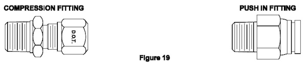
Compression fittings. Compression fittings have three main components; the main body, the compression sleeve, and the nut. The main body also has a tube support sleeve. The support sleeve prevents the air line from collapsing and allows the compression sleeve to make a proper seal with the air line. If an existing air line is removed, it can be reused without replacing the compression sleeve which would require cutting off the end of the air line. If the support sleeve is removed with the air line and the line must be cut, a new support sleeve must be used. Nuts and compression sleeves can be replaced without replacing the main fitting body. When tightening a new compression sleeve, the nut must be tightened enough to slightly crush the compression sleeve and create a leak-free air seal. Refer to Parker Hannifin Corporation for detailed tightening or re-tightening instructions.
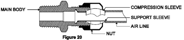
Push-in fittings. Push-in fittings make installation and removal of air lines easier. There is no tightening procedure to secure and seal the air line. The push-in fittings are reusable. To install an air line, make sure the end of the line has a good square cut. When cutting the line, it is best to use a good scissor-type tube cutter to prevent the line from being crushed while cutting. Push the line into the fitting until it bottoms out. Pull back on the line to make sure it is locked in place. To remove the line, push the locking ring toward the main body of the fitting then pull the line from the fitting. It will be easier to remove the air line if the air pressure is removed from the circuit. When removed, the end of the line will show some grip marks. It is best to cut off enough line to remove these grip marks. If the grip marks are not removed, the connection may leak.

3-2.3.4 Air manifold check valves. Standard air manifolds have a right and left check valve. The check valves perform two functions. They prevent air from flowing from the high-pressure airbag to the low-pressure airbag when both raise valves on the manifold are opened. They also prevent air from flowing from the airbag back to the air supply when a raised valve is opened. To date, I know of no air manifold check valve ever being replaced.
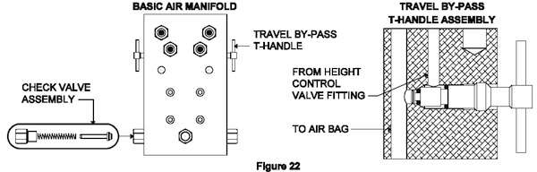
3-2.3.5 Travel by-pass T-handle. The by-pass T-handle is not on all air manifolds. The T-handle was added as an aid to the vehicle manufacturers. When open, air from the height control valve by-passes the traveling valve and is directed to the airbag. This allows the vehicle manufacturer to use shop air to keep the vehicle at ride height during the manufacturing process without having to energize the travel solenoid valves. The only real problem the T-handle has caused is the manufacturer will sometimes forget to close the T-handle when the production of the vehicle is complete. If a T-handle is open, any time the vehicle is raised, lowered or leveled, any corner with an open T-handle will return to ride height, depending on the available air supply. The by-pass T-handles should not be used as an emergency by-pass by the vehicle operator. Most air manifolds are mounted under the vehicle in areas with limited access. Turning the T-handle will cause the vehicle to move up or down which will be a hazard to anyone under the vehicle.
WARNING: DO NOT CRAWL UNDER A VEHICLE UNLESS THE FRAME OF THE VEHICLE IS PROPERLY SUPPORTED. DO NOT USE THE AIR SUSPENSION OR LEVELING JACKS TO SUPPORT THE VEHICLE WHILE UNDER THE VEHICLE.
3-2.4 The auxiliary air compressor. Air leveling systems have a program called the “sleep mode”. The sleep mode monitors the levelness of the vehicle and if needed, the system will “wake up” and re-level the vehicle. Because this happens when the vehicle engine is not running, it is possible the vehicle air supply will not be adequate to re-level the vehicle.
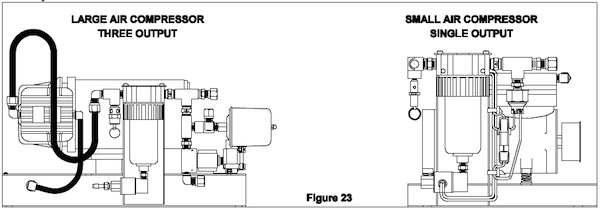
This is the primary job of the auxiliary air compressor, to supply air to the leveling system air manifolds for re-leveling the vehicle when in the sleep mode. The auxiliary air compressor is also used on some vehicles to maintain an auxiliary air tank to supply air to vehicle air equipment such as room air seals or toilets. Some manufacturers even allow the auxiliary air compressor to maintain minimum air pressure in the vehicle’s main air tanks. Of course, this means there are different size air compressors and many different compressor/valve/output arrangements. HWH uses two basic 12-volt compressors.
They are both Thomas compressors. One has a larger airflow capability than the other. The smaller compressor develops .43 cfm at 60 psi and .27 cfm at 100 psi. The pressure relief for the smaller compressor is normally set at about 110 to 115 psi. The larger compressor develops .95 cfm at 100 psi and .70 cfm at 140 psi. The relief for the larger compressor may be set as high as 140 psi.
When dealing with air compressor issues it may be best to contact HWH for a specific system or component drawings or diagrams.
Single output compressors are fairly simple.
The compressor is supplied power through a relay controlled by a + 12 volt signal from the HWH control box. Normally that signal goes through a pressure switch so the compressor will only run if the air pressure available from the vehicle air supply is low. The relay and pressure switch is part of the compressor assembly. A few systems run the HWH control signal directly to the compressor control relay so the compressor runs any time the HWH system calls for the compressor.
Multiple output compressors will be more complex with different wiring, pressure switch and valve arrangements. One output may be controlled by a valve; another may be controlled by a pressure switch. The control signal for air leveling will always come from the HWH control box. The control signal for other outputs will come from vehicle controls. Possibly, an auxiliary output may be controlled by a pressure switch that switches battery power. That way any time there is low air pressure on that particular circuit, the compressor will run. There may be a dash switch to control the air compressor.
As you can see, with the many variations available, especially with multiple output compressors, it is important to get the correct drawings and diagrams for diagnostic help.
The small compressor requires a 10 amp fuse and the large compressor requires a 30 amp fuse. Neither compressor is a sealed unit so they must be protected from dirt and moisture such as caused by road spray from tires.
3-2.5 Specialty air manifolds. There are many variations of air leveling manifolds but there are two that are different than the basic manifolds and also very common. Both manifolds are tag axle manifolds.
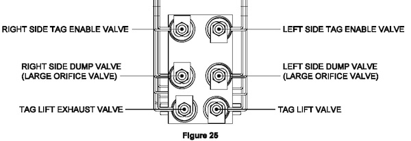
One is an eight-valve tag lift manifold used to control the tag lift mechanism. Six of the valves are normal travel, lower and raise valves. One of the remaining valves is the tag lift valve and supplies air to the tag lift mechanism to lift the tag axle. The other remaining valve is the tag lift exhaust valve. This valve exhausts air from the tag lift air bags to lower the tag axle. The lower valves, the tag lift valve, and the tag lift exhaust valve are different than the standard air manifold valves. They are the large orifice valves. When traveling or performing a leveling procedure, the 6 main tag axle valves work in unison with the drive axle valves. The tag lifts exhaust valve is on anytime the tag axle travel valves are on. When executing a tag lift procedure, the tag axle travel valves are turned off, the tag axle dump valves are turned on and the tag lift valve is turned on. This exhausts air from the tag axle airbags and lifts the tag axle.
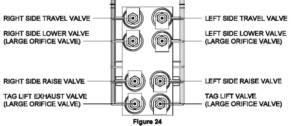
The other manifold is a six valve tag lift manifold. This manifold has two tags enable valves (a right and a left), two exhaust valves (a right and a left), a tag lift valve and a tag lift exhaust valve. The tag enables valves to connect the tag axle airbags to the drive axle airbags. These valves are on (open) any time the system is in the travel mode, a leveling mode (manual or automatic) and when performing an all raise or all lower function. The tag enables valves are turned off if a tag lift function is performed. When a tag lift function is performed, the tag enables valves are turned off, the tag exhaust valves are turned on (this empties the tag axle airbags) and the tag lift valve is turned on. This supplies air to the tag lift assembly to lift the tag axle. When in the travel mode or any time the tag enable valves are on, the tag lift exhaust valve is on. This exhausts air from the tag lift mechanism to lower the tag axle back to the ground. The valves used on this manifold are the same as the valves used on the standard air manifolds except for the two exhaust valves. They are a different part number and have a larger orifice to exhaust the air quicker.
3-3 System plumbing. Although there will be slight variations in the plumbing between different manufacturers and vehicles, the basic plumbing of the HWH equipment is fairly consistent. One variation depends on the number of airbags on each side of an axle. Some suspensions use one bag per side; some use two bags per side. When two bags are used, they are plumbed together. Some manufacturers tee the bags together after the HWH air manifold and some plumb in one line per bag to the manifold. The following diagrams show several ways the HWH equipment may be plumbed into the suspension. An important thing to note is the position of check valves for the air compressor. It is important that the air lines between the auxiliary air compressor and the HWH leveling manifold air supply are checked so the air compressor is not trying to feed the vehicle air supply while leveling the vehicle. When not checked properly, the auxiliary air compressor may not be able to supply enough air to level the vehicle while trying to fill the suspension or auxiliary air tanks.
Figure 26 is a standard air leveling system with one airbag per corner with no tag axle
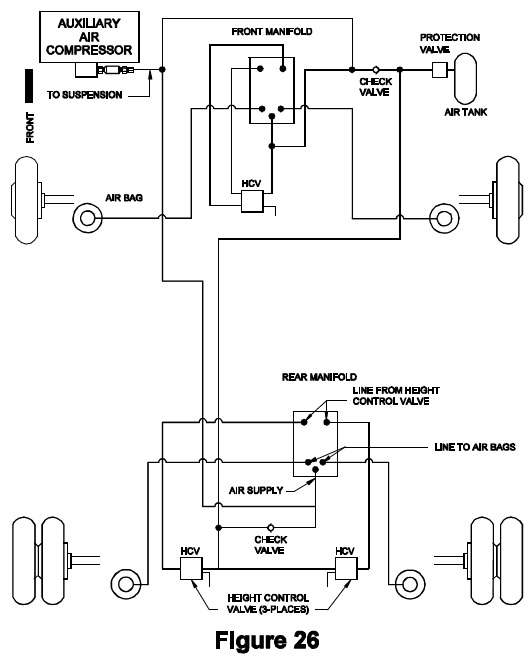
Figure 27 is an air leveling system with two airbags per corner with a tag axle. The tag has one airbag per side and is controlled by the drive axle height control valves. The front and drive axle bags are plumbed independently to the leveling manifolds.
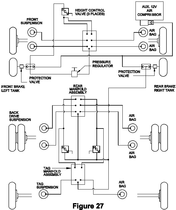
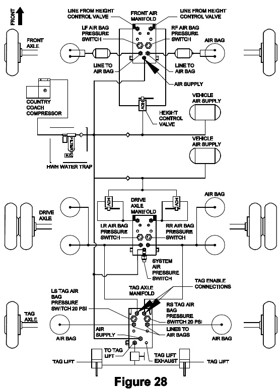
Figure 28 is an air leveling system with two airbags per side on the drive axle only. The bags tee together before the leveling manifold. The drive axle height control valves control the tag axle and the system has a tag lift controlled by the HWH tag axle manifold.
The following diagrams show detailed connections for several styles of manifolds.
Figure 29 is a front air manifold with two 20 psi airbag pressure switches and a single airbag connection for each side.
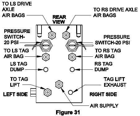
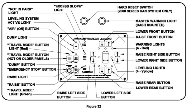
Figure 30 is a drive axle manifold. It has two 20 psi airbag pressure switches and an 85 psi system pressure switch. This manifold has connections for two airbags on each side. Figure 31 is a tag axle manifold. It has two 20 psi airbag pressure switches. This manifold has no height control valve connections but is connected to the left and right side drive axle airbags. The drive axle height control valves control the tag axle airbags. There is a single airbag connection on each side and a connection for the tag lift mechanism.
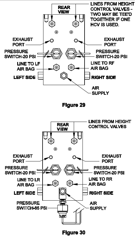
Figure 31 is a tag axle manifold. It has two 20 psi airbag pressure switches. This manifold has no height control valve connections but is connected to the left and right side drive axle airbags. The drive axle height control valves control the tag axle airbags. There is a single airbag connection on each side and a connection for the tag lift mechanism.
3-4 System wiring. The system wiring, like the plumbing, can vary between manufacturers and vehicles. With the older 500 and 600 series leveling systems, the wiring was very consistent and only changed if a tag axle lift was incorporated into the system. Even vehicles with a tag axle were not complicated. When traveling or leveling, the tag and drive axles were controlled as one axle. If a tag lift was used, relays in the control box isolated the tag from the drive axle so the tag axle airbags could be dumped and the tag lifted. The basic, single control box 2000 series CAN air leveling system is wired much like a 500 or 600 series system. The two main differences are the CAN system has the ability to recognize a signal from the transmission speed switch for the “Dump” and “Raise” functions and the CAN control box uses four power inputs instead of the three that the 500 and 600 systems used. Electrical information for specific systems will be discussed in greater detail in Lesson 14 of the HWH Online Technical school.
It is important to get specific wiring diagrams and/or system schematics when addressing wiring issues. Repair manuals are available for the 500 series, 600 series and the single control box 2000 series CAN leveling systems. These manuals contain basic wiring diagrams for these systems.
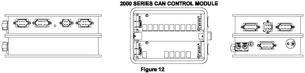
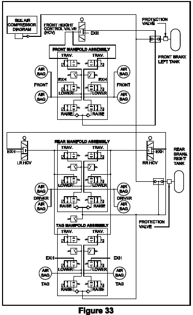
3-5 The five basic “modes” of the air leveling system; travel mode, raise or dump mode, leveling mode, sleep mode and excess slope mode. Touch panel lights and buttons are shown in Figure 32.
3-5.1 Travel Mode. The travel mode is when the suspension height control valves, through the HWH travel valves, control the vehicle ride height. The vehicle ignition must be on for the system to be in the travel mode. In the travel mode, the HWH air manifold travel solenoid valves will be on. For vehicles with a tag lift manifold, the tag enables valves will be on in the travel mode. This allows the suspension height control valves to control the suspension airbags and keep the vehicle at ride height. The system touch panel has either a “TRAVEL” or “TRAVEL MODE” indicator light that will be on when the system is in the travel mode and the ignition is on. If an airbag or the system has low air pressure the travel/travel mode light will go out and a dash warning light will come on.
Even though the travel/travel mode light is off when air pressure is low, the air manifold travel valves will still be on (open).
If the vehicle has a tag axle with a tag lift, the travel/travel mode light will not be on if the tag lift is on. When a tag lift function is performed, the front and rear travel valves remain on so the height control valves can maintain proper vehicle ride height. With early systems, the system will be in the travel mode anytime the ignition is on and the HWH touch panel is off. Later systems have a “TRAVEL MODE” button that must be pushed to return the system to the travel mode, even if the touch panel has been turned off. With any air leveling system, the system will be in the travel mode anytime the ignition is on and the parking brake is released; except when the “RAISE” or “DUMP” buttons are being used.
3-5.2 Raise or Dump mode. Most system touch panels have a “RAISE” and a “DUMP” button. A few air leveling panels will not have the “RAISE” button. The raise and dump buttons are used to raise or lower all four corners of the vehicle at the same time. The system is designed to allow the use of the raise and dump buttons while the vehicle is moving, such as getting over a curb or under a tree limb. It is important that the vehicle is moved at very slow speeds for short distances when the raise or dump button is used.
The “RAISE” or “DUMP” buttons will function with the system on or off but not while in an automatic leveling mode. The parking brake does not need to be set to use the raise or dump button. With most 500 and 600 series control boxes, the buttons are momentary and will only dump or raise while the buttons are pushed. After a two-second delay, the suspension returns to ride height when the raise or dump button is released if the ignition is on. The 2000 series CAN system will latch the raise or dump feature in if the transmission speed switch is connected to the HWH control box. This means the vehicle can be moved without holding the dump or raise button.
It is important to understand that if the system has the latch in feature, the vehicle will lower or raise to its maximum capability when the dump or raise button is pushed.
The system will unlatch and return to ride height when a pre-programmed speed, usually 15 mph or less, is reached. With any system, the touch panel will turn off after the raise or dump button is used.
The raise and dump features are supplied with most HWH air leveling systems. This section and HWH operator’s manuals explain how to use the “RAISE” and “DUMP” buttons and how the system will react when using the buttons. The appropriate use of these features is determined by the vehicle manufacturer.
3-5.3 Leveling modes. The leveling mode has two options; manual control or automatic control. For either method of leveling, the touch panel must be turned on by pushing the “AIR” button one time. With early systems, the panel could be turned on with the ignition on or off. If the ignition was on, the parking brake had to be set. It the ignition was off, the parking brake did not have to be set. With later and the present-day systems, the ignition must be on and the parking brake must be set to turn the touch panel on. Once the panel is on, the ignition can be turned off.
When initially leveling the vehicle, manually or automatically, it is best to have the vehicle engine running. This creates a better air supply when leveling the vehicle with a raise function. The touch panel has four yellow level indicator lights; a front light, a rear light, a left sidelight, and a right sidelight. These lights will work when the touch panel is on. A lit yellow level light means a side or end of the vehicle is low. When all four-level indicator lights are off, the vehicle is level. A lit level light also means the opposite side or end is high. It is possible to attempt to level the vehicle by lowering the high side or end.
3-5.3.1 Manual leveling. When the touch panel is on, the up and down arrows on the right-hand side of the touch panel can be used to manually level the vehicle. The up arrows open the raise valves and lift the vehicle. The down arrows open the lower valves and lower the vehicle. Each button raises (up arrows) or lowers (down arrows) two corners of the vehicle at the same time. If the vehicle has a tag axle, the tag axle will do the same thing as the drive axle.
Example: If the right side down arrow is pushed, the system will exhaust air from the right front airbag(s), the right side drives axle airbag(s) and if equipped with a tag axle, the right side tag axle airbag. If two-level lights are on at once, it is best to put out the side level light before working on the front or rear level light. If desired, you can use a down arrow opposite a lit level light to lower the high side or end of the vehicle.
Example: The left side level indicator light is on. This means the right side of the vehicle is high. Push the right side down arrow to exhaust air from the right side front, rear and tag (if so equipped) airbags to lower the right side. If all air is exhausted from the right side airbags and the left side level indicator light is still on, push the left side up arrow to add air to the left side airbags to raise the left side of the vehicle. The same thing can be done for a lit front or rear level indicator light. If an airbag pressure switch for the end that is being lowered comes on, the system will stop the lowering process even though the down arrow is being pushed. Air will have to be added to the low end of the vehicle to try and level the vehicle.
3-5.3.2 Automatic leveling. There have been different leveling programs in the past and will be different leveling programs in the future. When trying to determine the program of a specific control box, it may be necessary to get the program number off of the control box computer chip. For 2000 series CAN systems this will be the computer chip from the central control module “mother” board. For chip location in the control, box refers to section 3-2.1 of this lesson or contact HWH technical service. If the program number has a – number, (example: 9636-5) the dash number is also important. The program number will allow HWH personnel to determine the exact parameters the system will react to.
The basic bi-axis leveling concept is always used; level the vehicle side to side (if needed) then front to rear and raise or lower two corners of the vehicle at a time when leveling. But there have been and will be different ways the system will react. Maybe all the air will be dumped from the airbags before leveling. Maybe air will be added to the rear airbags before leveling. One program will react to airbag pressure switches being on differently than another program. It is important to know how the specific program you are dealing with will react.
The leveling program in use at the time of this publication is as follows:
1.) Push the “AIR” button one time. The ON light above the “AIR” button will be on steady.
2.) Push the “AIR” button a second time. The ON light will start to flash and the auto-leveling process will begin.
3.) The system will start by exhausting air (lowering) the high side or end of the vehicle. The high side or end will be opposite a lit yellow level indicator. The system will always start with a side if aside and end level indicator light is lit. Example: The right side and front level indicator lights are on. The system will start dumping air from the left side. If the system cannot achieve a level position, all level indicator lights off, while exhausting air, the system will switch to adding air to the low side and/or end of the vehicle to achieve a level position by raising the low side and/or end of the vehicle.
4.) When all four yellow level indicator lights are off, the ON light above the “AIR” button will flicker dimly. The system is now in the SLEEP mode. (Explained in 3-5.4) The ignition can be turned off and the system will stay in the sleep mode. Ten minutes after the ignition is turned off, the ON light will turn off. This is a power-saving feature. The system will still be in the sleep mode even though the ON light is off. If the ignition is turned on, the ON light will start to flicker dimly again.
5.) If all of the yellow level indicator lights will not turn off, the panel will exhibit the “EXCESS SLOPE” light. (Explained in 3-5.5)
The following five paragraphs explain some of the automatic leveling program features in greater detail.
When lowering aside, the procedure is a timed sequence. If the sidelight goes out while exhausting air and no other level indicator light is on, the system will stop the leveling procedure. If a front or rear level indicator light is on after the side light goes out while exhausting air, the system will start lowering an end of the vehicle. If the side level light remains on steady for 45 seconds while exhausting air, the system will stop exhausting air from the high side and start adding air to the low side, the side with the lit level indicator light.
When lowering an end, the procedure is a timed sequence or interrupted by an airbag pressure switch that comes on. When exhausting air from an end, if the lit end level indicator light goes out and all level indicator lights are off, the system will stop the leveling procedure. If the end level light remains on steady for 45 seconds while exhausting air, the system will stop exhausting air from the high end and start adding air to the low end, the lit level light. If either pressure switch for the end that is lowering comes on while exhausting air, the system will stop exhausting air from the high end and start adding air to the low end.
Whether lowering a side or an end of the vehicle, when the system switches to a raise function from a lower function, the system will not revert to a lower function during the existing leveling sequence no matter what level indicator light is on or turns off.
If a side level indicator light and an end level indicator light are on, once the sidelight is out, whether, during the lowering or raising process, the processor will attempt to level the vehicle front to rear to put the end level indicator light out. Once an end to end leveling process is started, if a side level indicator light comes back on, the processor ignores the side level light until the end level light is put out, then the processor will again work on the side level light if it is still on.
An important thing to understand about air leveling is the necessity of limiting motion in the vehicle during an automatic leveling process. Automatic air leveling may take longer on a windy day. If the processor is trying to turn a level indicator light off and that light “flickers”, the leveling process stops. The processor has to see that light on or off for 2 seconds before the leveling process will resume. If the light continues to flicker without being on or off for 2 seconds the processor will just wait and do nothing. Walking around in a vehicle can cause a level indicator light to flicker. If the flickering light stays on for 2 seconds, the leveling process will resume from the point where the light started flickering. If the flickering light stays off for 2 seconds, the leveling process will move to another lit level indicator light or declare the vehicle level if no other level indicator lights are on.
3-5.4 The SLEEP Mode. Air suspensions are not designed to be zero leak systems. This means that over a period of time (this time will vary from vehicle to vehicle) the suspension airbags can leak air. This can cause the position of the vehicle to change, possibly enough to go out of level. The sleep mode is a routine that will maintain the level position of a vehicle for an extended period of time. The sleep mode routine is only available if the automatic air leveling feature is used.
During automatic leveling, as soon as a level position is achieved with all four-level indicator lights turned off, the processor starts the sleep mode. The ON light will change from a flashing light to a dimly flickering light. The dimly flickering light indicates the system is in the sleep mode. Ten minutes after the vehicle ignition is turned off, the ON light will turn off. The system will remain in the sleep mode. If the ignition is turned on, the ON light will start flickering. In the sleep mode, every 30 minutes, the processor looks at the inputs from the level sensing unit. If an input is on, the processor now monitors the level sensing unit inputs. If the input stays on continuously for 1 minute, the system “wakes up” and starts the automatic leveling process. The leveling program in the sleep mode is the same as the initial automatic leveling program. If a level position with all four-level indicator lights off is achieved, the system returns to the sleep mode, looking at level sensing unit inputs every 30 minutes. The sleep mode is continuous until the “OFF”/ “EMERGENCY STOP” button is pushed, the “TRAVEL MODE” button is pushed or the parking brake is released if the ignition is on. The “OFF”/ “EMERGENCY STOP” or the “TRAVEL MODE” buttons will not shut the sleep mode off unless the ON light is flickering.
3-5.5 Excess slope. Excess slope happens when the system will not level the vehicle in the automatic leveling mode. The HWH touch panel has an “EXCESS SLOPE” light that comes on if the system goes into an excess slope situation. The “EXCESS SLOPE” light does not function when leveling manually. Excess slope happens when a yellow level indicator light remains on steady, the system is in the raise mode to turn the level indicator light off and 15 minutes elapse without the level indicator light changing (no flickering). The “EXCESS SLOPE” light will now come on and the leveling process will cease. A key to the excess slope, especially if checking the excess slope routine, is that the yellow level indicator light must remain steady. Any time the light flickers, the 15 minute time starts over. Movement in the vehicle or wind can cause a level indicator light to flicker; this starts the 15 minute time over again, no matter how much of the 15 minutes has elapsed.
Once the “EXCESS SLOPE” light comes on, the ON light will go out. The “EXCESS SLOPE” light stays on until with the vehicle ignition on, the “TRAVEL MODE” button is pushed or the parking brake is released. If the “EXCESS SLOPE” light is on when the ignition is turned off, the light will go out 10 minutes after the ignition is turned off. If the ignition is turned on, the “EXCESS SLOPE” light will come back on. The leveling system can be turned on and operated manually, but the “EXCESS SLOPE” light will remain on. If the “EXCESS SLOPE” light comes on when re-leveling the vehicle while the system is in the SLEEP mode, the SLEEP model is discontinued. The processor does not monitor the level sensing unit inputs or try to re-level the vehicle again.
3-6 Tag dump. A tag dump system is a feature offered by the vehicle manufacturer. When making very sharp turns at slow speeds, especially when backing up, the tag axle tends to slide side to side. Dumping the tag axle airbags or dumping the tag airbags and lifting the tag axle will take the stress off the rear suspension, especially the tag axle suspension. Dumping the tag axle airbags also puts more weight on the drive axle. This can give the vehicle more traction on slippery or muddy surfaces. Some tag dump systems only dump the air from the tag axle airbags, other systems dump the air from the tag axle airbags and have a lift mechanism to lift the tag. The use of a tag dump feature is directed by the vehicle manufacturer. The control switch for the tag dump feature is supplied by the vehicle manufacturer. The tag dump feature is designed to be used only at slow speeds for short distances. The tag dump feature should be inhibited from being inadvertently engaged at normal traveling speeds. Inhibiting the use of the tag dump feature can be accomplished in several ways. With one manufacturer, the power for the tag dump switch is only present if the vehicle transmission is in neutral, reverse or first gear. Vehicles with a transmission speed switch can use the speed switch signal to inhibit the use of the tag dump feature when the vehicle is traveling at a speed greater than a predetermined speed programmed into the transmission speed switch. This speed normally will be 15 mph or slower.
To use a tag dump or raise function, the first thing that must be done is to isolate the tag axle airbags from the rest of the suspension. If the vehicle does not have an HWH tag axle air manifold, the valves and electronics to isolate and dump the tag axle airbags are supplied by the vehicle manufacturer. When the vehicle is equipped with an HWH tag axle air manifold, the HWH control system controls the tag dump or lift function. Whether the function is a tag dump or lifts function, the tag axle travel or tag enable valves are turned off. This isolates the tag axle airbags from the suspension controls. The tag dump valves are turned on to dump air from the tag axle airbags. If the vehicle has a tag lift controlled by HWH, the tag lift exhaust valve is turned off and the tag lift valve is turned on. Typically, the harness wire for the tag axle travel or tag enables valves is the same wire used to supply control power to the tag lift dump valve. The tag lift dump valve remains on while traveling to ensure the tag lift mechanism cannot try to lift the tag axle.
When the tag control switch is returned to the travel position, the tag dump valves are turned off and the tag travel or tag enable valves are turned on. If the tag air manifold controls a tag lift mechanism, the tag lift valve is turned off and the tag lift dump valve is turned on.
3-7 Schematic representations of air manifold functions. The basic operation of the air manifold and its components were discussed in section 3-2.3, but we now will look at some schematics of several different manifolds to show you how the air flows through the manifolds to perform travel, leveling and tag lift functions. The following schematics will be drawn with the valves or pressure switches open or closed as they would be for the function that is being performed. It is important to remember when viewing schematics in a normal manner, the components will be drawn in the normally off position. With the air leveling valves and switches, this would be with the valves closed and the pressure switch contacts close.
Remember that there are many variations of plumbing, air manifold, and tag axle arrangements. The following schematics are EXAMPLES of possible arrangements. You should contact the vehicle manufacturer or HWH Corporation for specific plumbing and air manifold arrangements for the vehicle that you are dealing with.
3-7.1 Travel mode schematic. The following schematics show the manifold valves in the travel mode; one has a standard tag axle manifold with no tag lift valves and one with no tag axle. Note: only the travel valves are open. The air can flow through the manifold to and from the height control valves. The height control valves maintain the proper travel height. All pressure switch contacts should be open at this time.
3-7.2 Leveling raise mode schematic. The following schematic is to raise the right side mode for leveling. The schematic shows a standard tag axle manifold with no tag lift valves. A schematic for a system with no tag axle would be the same except with no tag axle manifold. A rear raise would show both drive axle raise valves open along with both tag axle raise valves. Note that the only solenoid valves that are open are the three right side raise valves.
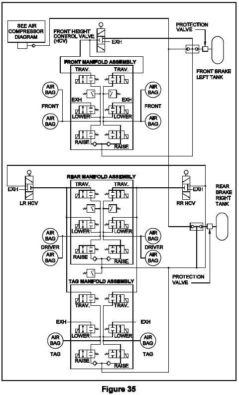
If the vehicle has a tag axle with an HWH system that uses a tag lift manifold with tag enable valve, the tag enables the valve will be open any time the HWH air leveling system is on. This connects the tag axle airbags to the drive axle airbags. A raise right side function would add air to the right side tag axle airbag along with the right side drive axle airbag(s). The next section is the Leveling lower mode. It shows an example of a system that uses the tag axle manifold with the tag enable valves.
3-7.3 Leveling lower mode schematic. The following schematic shows a tag axle system that used a tag axle manifold with tag enable valves. Note that although the manifold has tag lower valves, these valves are not used is a leveling lower procedure. The tag enables valves are open which connects the tag axle airbags to the drive axle airbags. The tag axle airbags are exhausted through the drive axle lower valves. The tag lift exhaust valve is also on. This valve is tied electrically to the tag enable valves. This ensures the tag lift mechanism is not trying to lift the tag axle when traveling or when in a leveling mode. Note that with the air being exhausted from the right side airbags, the right side airbag pressure switch contacts are now closed. Although the contacts are shown closed, the pressure switch contacts would not close just because a lower function is done. The air pressure in the airbags must decrease to the pressure switch setting for the contact to close.
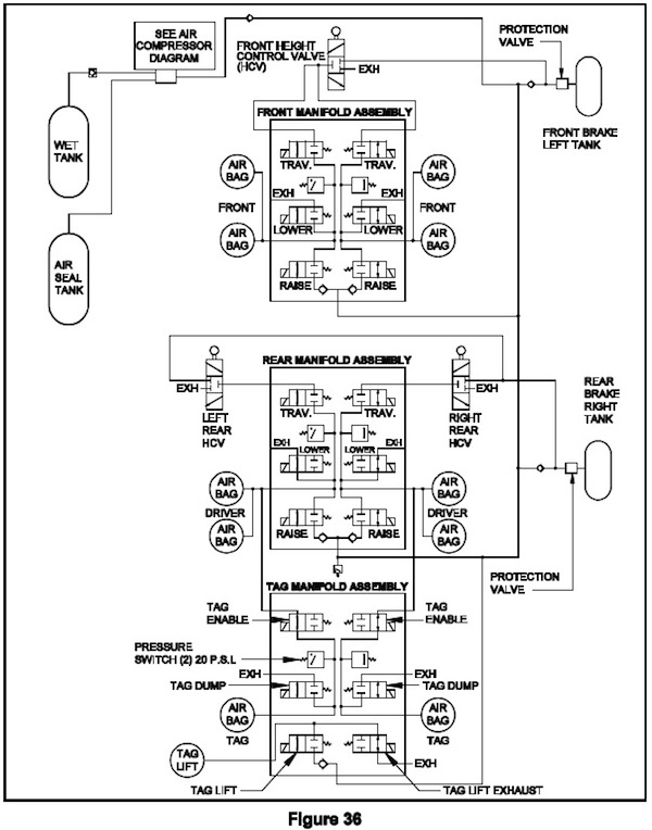
The above schematic could also represent a system without a tag axle. Just disregard the tag axle manifold and all tag axle connections and information. If the system used a standard tag axle manifold or a standard style tag axle manifold with tag lift valves, the tag axle travel valves would not be on. The tag axle lower valves would both be on to do a rear lower function.
3-7.4 Tag dump/lift schematics. The following schematics are the three main tag dump or tag lift arrangements. The valves are shown in the tag dump or lift mode. When the tag control switch is in the off or travel position, the valves will be in the travel mode or a leveling mode. The travel and leveling mode valve positions are shown in 3-7.1 through 3-7.3. Some tag axle systems that use a standard tag axle manifold and a tag lift have a wire in the HWH harness to control the tag lift mechanism.
A system with standard tag axle manifold Tag dump only
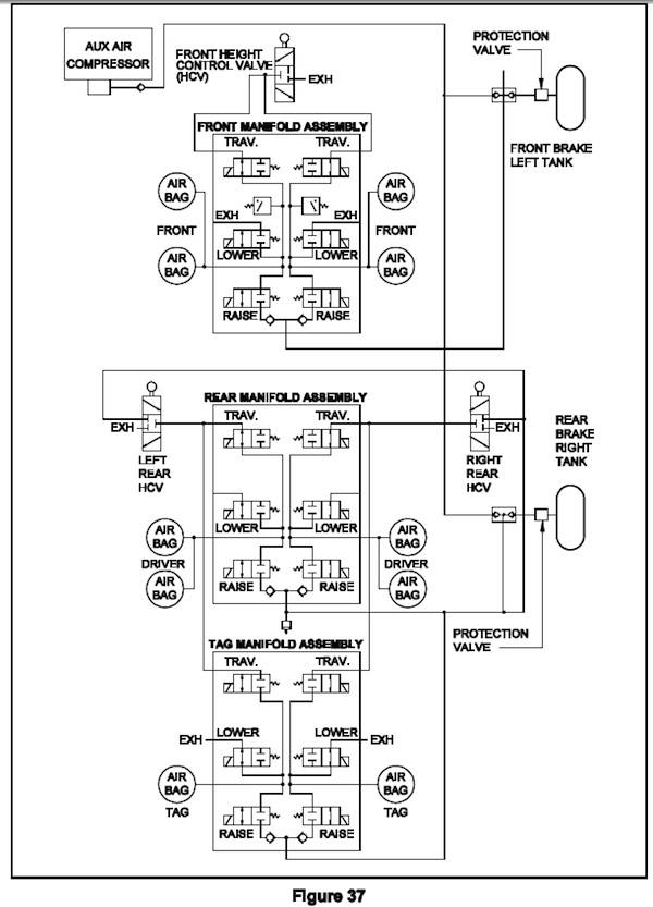
With this system, the front and drive axle manifold valves are in the normal travel position, the travel valves are open with the other valves closed. On the tag axle manifold, the travel valves are closed and both lower valves are open. This exhausts the tag axle airbags. This is a tag dump; a tag lift system can now be used if so equipped.
A system with tag lift manifold. With tag enable valves
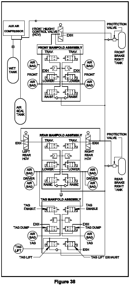
A system with standard tag axle manifold. With tag lift valves
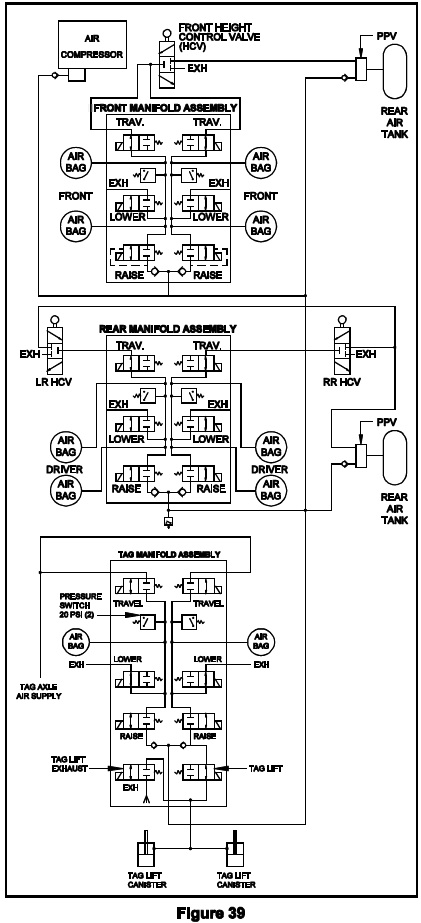
Both of these manifolds are equipped with tag lift valves. In the tag lift mode, the travel valves (or tag enable valves) are off. This isolates the tag axle airbags. The lower (tag dump) valves are open to exhaust the tag axle airbags. The tag lift valve is open. This supplies air to the tag lift mechanism. In the travel mode, the travel valves (tag enable valves) are open so the tag axle airbags are inflated. The tag lift dump valve is open to exhaust air from the tag lift mechanism. The tag lift dump valve is open any time the travel (tag enable) valves are on.
3-8 Schematic representations of the HWH auxiliary air compressor. The following schematics are for a single output air compressor and a multiple output air compressor. The wiring diagrams for these compressors are also included. It is easier to understand the operation of the air compressor by associating the air and electrical drawings. Remember, these are only two of the many different combinations that are available. It is important to access the corresponding drawings for a specific compressor arrangement that you are dealing with.
3-8.1 The single output air compressor. Typically, the single output auxiliary air compressor is used for air leveling systems but it has been used to maintain an auxiliary air tank for room extension air seals also. Air compressors used with air leveling systems are controlled by the air leveling system controls. If the air compressor is used for an auxiliary air tank, the vehicle manufacturer would supply the air compressor control. It may operate off direct battery power with a pressure switch or it may have some type of dash control. You will have to refer to manufacturer information about these types of systems. When the auxiliary air compressor is used for a leveling system, a +12 volt signal from the air leveling controls turn the compressor on. The compressor signal is supplied by the control system anytime a manual or automatic raise function is called for. If the compressor is equipped with a pressure switch, the compressor will not run if there is adequate suspension system air pressure, usually 85 to 90 psi or more.
When the system air pressure drops below 85 to 90 psi, the pressure switch contacts will close and the air compressor will run, supplying air to the air leveling manifolds. The compressor will turn off when the pressure switch contacts reopen, normally 110 to 115 psi. If a pressure switch is not used, the compressor will run anytime a manual or automatic raise function is called for. The water trap has a normally open valve to relieve compressor pressure and drain the water trap. The water trap valve will close any time the compressor is running.
Single output air compressor air schematic
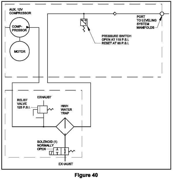
Single output air compressor wiring diagram
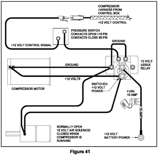
3-8.2 Multiple output air compressor. The multiple output auxiliary air compressor not only supplies air to the leveling system but can also maintain an accessory tank for room air seals or other air equipment and/or the main coach air supply tanks. There are different ways this type of air compressor can be set up so it is important to get the correct air and wiring diagrams for a specific air compressor.
The compressor represented in the following drawings is a three-port compressor that is used to maintain an accessory tank and the main coach tanks. One port is for the leveling system, one is for an accessory air tank and one is for the main vehicle air tanks.
The accessory tank is maintained at all times with battery power switched through a pressure switch on the air compressor. If the pressure in the accessory tank drops to between 70 and 80 psi, the pressure switch contacts should close and the compressor should come on. The compressor should turn off when the pressure in the accessory tank reaches 90 psi and the pressure switch contacts open.
The port for the main vehicle air tanks is controlled with a normally closed solenoid valve. The compressor pressure switch also controls when the compressor will run. The vehicle manufacturer supplies a dash switch to control this maintenance function. Any time the dash switch is on, the solenoid valve for the vehicle air tanks will be on. If the vehicle tanks or the accessory tank air pressure drops below 70 to 80 psi, the pressure switch contacts will close and the compressor will run. When the pressure increases to 90 psi, the pressure switch contacts will open and the compressor will turn off. The solenoid valve for the vehicle air tanks will remain open as long as the dash compressor switch is on.
The port for HWH air leveling manifolds has no regulating valve or pressure switch. Whenever a manual or automatic raise function is performed, the HWH air leveling system controls to send a +12 volt signal to the air compressor relay. The compressor will run as long as the signal from the leveling controls is present.
The water trap has a normally open solenoid valve to relieve compressor pressure and to drain the water trap. This valve will close any time the air compressor is running.
Multiple Output Air Compressor Air Schematic
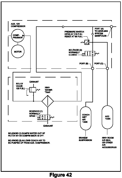
Wiring diagram
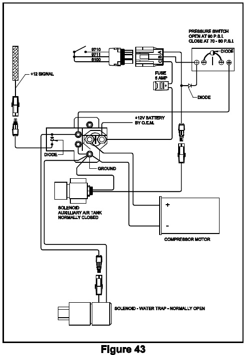
3-9 General diagnostics for air leveling systems. The hardest part of diagnosing air leveling system problems can be deciding where the problem lies. When dealing with air leveling systems, you are dealing with two individual but combined systems; the vehicle suspension system and the HWH air leveling system. Understanding the basic function of the air leveling system makes this much easier. As stated in section 3-2.3 of this lesson, the air manifolds have three functions:
1. Allow air to pass back and forth through the manifold so the height control valves or the tag axle air supply can regulate air in axle airbags when the vehicle is traveling. This would be the travel valves or the tag enable valves.
2. Direct air into the axle airbags or a tag lift mechanism to raise the vehicle or lift the tag axle. This would be the raise valves or the tag lift valve.
3. Exhaust air from the axle airbags or a tag lift mechanism to lower the vehicle or lower the tag axle from a tag lift position. This would be the lower valves or the tag lift exhaust valve.
These three functions mean this; the HWH valves can only open to allow air to flow through the valve seat or close to stop air from flowing through the valve seat. Except by opening or closing the valves, the HWH system cannot regulate how high or how low the vehicle can be raised or lowered. How much the vehicle can raise or lower is a function of available air supply and pressure or the suspension components such as, but not limited to, height control valves, torsion bars, and shock absorbers.
WARNING: DO NOT CRAWL UNDER A VEHICLE UNLESS THE FRAME OF THE VEHICLE IS PROPERLY SUPPORTED. DO NOT USE THE AIR SUSPENSION OR LEVELING JACKS TO SUPPORT THE VEHICLE WHILE UNDER THE VEHICLE. AIRBAGS MAY DEFLATE OR JACKS MAY RETRACT CAUSING THE VEHICLE TO DROP SUDDENLY. THIS CAN CAUSE SERIOUS INJURY OR DEATH.
From an HWH standpoint, you only have to check that the manifold valves are opening or closed when required. Checking this could require being under the vehicle to make certain tests. You may have to check the voltage at a valve or even remove an air line to get a positive result. Sometimes physically checking the airbags will require you to get under the vehicle. PAY ATTENTION TO THE ABOVE WARNING, IT MAY SAVE YOUR LIFE.
The biggest mistake technicians make when diagnosing problems is watching the vehicle when doing a raise or lower function. When air is added to or exhausted from airbags, weight is transferred to or removed from the other side or end of the vehicle. This will make a side, end or corner of the vehicle raise or lower even though no air is added to or exhausted from those airbags. An example would be if you exhaust air from the right side of the coach, the right side seems to lower as it should. But if only the right rear airbag is emptied, that will shift weight to the right front airbag. The air in the airbag will compress. The right front corner will lower, giving the impression the system is working when in fact, there is an issue with the right front lower valve, controls for that valve or something in the suspension. When checking raise, lower or travel functions, you have to pay attention to what the axle airbags are doing. The best way to do this is to always start with the vehicle at the proper ride height or at least some air in the airbags. If the vehicle will not go to ride height, use the manual function of the touch panel to air up the airbags. If the airbags will not inflate, you have your diagnostic starting point.
When you begin, physically check all front, drive and tag axle (if so equipped) airbags. It is best to actually push on the bag. Use a rounded end stick such as a broom handle if needed to reach the airbag. NO SHARP OBJECTS. Normally, a visual check will work but the push method is the most reliable. If the airbag has air in it, the bag should feel hard and have no wrinkles. A deflated airbag will usually be wrinkled and soft. Checking airbags is like checking tires without a pressure gauge.
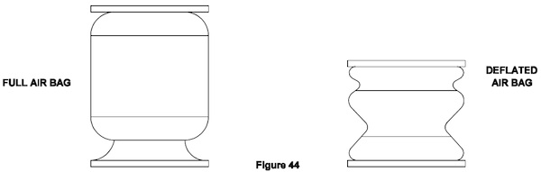
For the discussion at this time, we will say all of the suspension airbags have ample air pressure. Always start your tests in the manual mode. If the system will not function manually, it most likely will not function in the automatic mode. Since the mid-1990s, systems with airbag pressure switches will inhibit a front and/or rear lower function as the air pressure decreases. This can inhibit checking the airbags. Before starting your tests, you should unplug the airbag pressure switches. This will allow you to completely deflate all airbags. It is probably easiest to do this at the control box. Remember to plug the pressure switches back in when the testing is complete.
Start with any set of manual raise (up arrow) and lower (down arrow) buttons. It is not important which set you start with, only that you check all four sets of manual buttons. Where you start, push and hold the down arrow until you can hear no more air exhausting. Check all of the axle airbags. Only the bags relating to the down arrow that was pushed should be empty. Example: If the right side down arrow is pushed and held, all air from all right side airbags, including tag axle airbags if so equipped, should become completely deflated. If bags that should, don’t empty or bags that shouldn’t do, this is where you start your diagnostics. If a bag doesn’t empty, do you have at least 8 volts between the power and ground wire for the solenoid valve? If you have good voltage, the valve is bad, the exhaust port is plugged or an air line is pinched or plugged. If the voltage is low or not present at all, start electrical diagnostics. The problem will be a connection, wire, ground, control box or power supply. If a bag empties and shouldn’t, why do you have voltage to the valve? Usually, you will see the wrong airbag is being exhausted. In this case, maybe the right front bag will not deflate but the left front bag does. Either the wiring to the valves is crossed or the plumbing is crossed. If all right side airbags deflate as they should and no left side airbags deflate, push and hold the right side up arrow for 5 to 10 seconds. Check the right side airbags. All of the right side airbags should now be inflated. Without having pressure gauges installed in the airbag lines, it would be hard to tell if the air is being added to any left-side airbags. If the proper airbags deflated, the plumbing should not be an issue, but the wiring maybe. If bags deflate but will not inflate, check voltage and wiring for the corresponding raise valves. Check the air supply to the manifold. It is important to check all three other sets of up and down arrows. If all four sets of up and down arrows function properly, proceed to test the system in the automatic mode. Any problems in the automatic mode should be a control box, pressure switch or level sensing unit problems.
3-9.1 Diagnosing pressure switch problems may require being under the vehicle. Don’t forget the above WARNING. If airbags will not deflate, a pressure switch with closed contacts could be inhibiting an airbag from exhausting. With 20 psi of pressure in an airbag, the bag will look and feel inflated. If necessary, use the manual up arrow to make sure there is ample air in the airbag. Unplug the pressure switch and retry. If the bag can now be exhausted, that indicates a faulty pressure switch. If the master warning light stays on, unplug all switches including the system air pressure switch. If the light goes out, plug the switches back in one at a time. If an airbag pressure switch is on, there is a one minute delay before the master warning light will come on. Wait several minutes between plugging in system warning switches to get an accurate account of which switch may be causing the problem. The system air pressure switch will turn the master warning light on immediately. You can also do a continuity test at the control box to check pressure switches. Anytime the system and the airbags have ample pressure, the pressure switch contact should be open, with no continuity. With empty airbags and low system pressure, the pressure switch contacts should be closed; continuity across the two pressure switch wires. Unplug the pressure switches at the control box and check between the pressure switch wires and vehicle ground. When doing continuity tests, you have to make the same test at the pressure switches to eliminate harness issues. Performing continuity tests at the control box identify the problem pressure switch circuit.
3-9.2 Diagnosing travel mode issues will normally require getting under the vehicle. Again, pay attention to the WARNING. Start with the vehicle engine running and full pressure in the vehicle suspension air tanks. Depending on the system, push or push and hold the “DUMP” button. If the system has a momentary DUMP button, the system will return to the travel mode after the button is released. Before releasing the DUMP button after the air stops exhausting, turn the ignition off. After the air stops exhausting, check that all airbags, including tag axle airbags, if so equipped, are completely empty. Put the system in the travel mode. The ignition must be on. Make sure the TRAVEL light on the touch panel is on. All airbags should inflate and raise the vehicle to the travel position. If the airbags are inflating but the vehicle will not return to ride height, the problem is in the vehicle suspension. If any airbag does not inflate, you must check to see if the travel or tag enable valves are opening. Check to make sure there is adequate voltage to the travel or tag enable valves. Because travel valves are on either one fuse (500/600/680 systems) or two fuses (2000 CAN systems, three fuses with a tag axle), there will be more than one empty airbag (or pair of airbags) if a fuse is blown.
If the system has tag enable valves, there is one fuse for both enable valves. If travel or tag enable fuse is blown, unplug the valves involved, replace the fuse and with the system in the travel mode, plug the valves in one at a time until the fuse blows. If the fuse blows with no valves plugged in, the problem is the harness or control box. If there is adequate voltage to the valves and no fuses are blown, you will have to check if the valves are opening. You will have to get under the vehicle to perform this test so again, pay attention to the WARNING toward the beginning of this section, 3-9.
First, manually inflate all airbags. Check that all airbags have inflated. Make sure the ignition and leveling system is off. At the manifold, disconnect the air line between the height control valve and the suspected travel valve or disconnect the tag enable connection for the suspected tag to enable the valve. Turn the ignition on and put the system in the travel mode. The airbag(s) for the disconnected solenoid valve should deflate. If the airbag(s) deflate, the problem is in the vehicle suspension. If the airbag(s) do not inflate, the solenoid valve should be replaced.