HCV=Height Control Valve
PTC=Push to Connect
*Refer to installation instructions for your suspension.
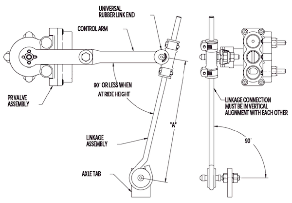
1. Determine if the HCV control arm is in the proper position for installation. Alignment indicator nub should be clocked at a specific orientation which is dependent upon valve installation. All valves must be installed in accordance with Link installation instructions.
2. Make sure that the control arm and linkage are in the appropriate and recommended. Improper installation may cause damage to components of the HCV and linkage or other suspension components.
Refer to the figure below for proper angles when at ride height.
3. Make sure all airlines are cut flush and contain no burrs. Also, check that all airlines are firmly pressed into all PTC fittings. Soap spray should be used to determine leakage around air hose fittings.
Note: Under normal operation, air will exhaust from underneath the interface cap of the HCV. This should not cause alarm or require replacement of the HCV.
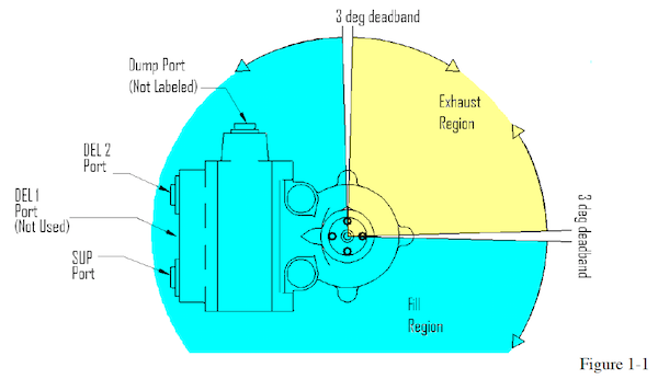
4. To ensure HCV is working properly, disconnect the linkage from the control arm and raise the control arm approximately 20o above horizontal. Air pressure should inflate the air springs and raise the suspension. Refer to Figure 1-1.
If the air springs do not inflate:
a) Verify that the air supply pressure is sufficient to open the valve (usually greater than 75psi).
b) Recheck the air lines for proper port connection.
c) If the valve has a dump feature, confirm the dump switch is not activated.
d) Determine if the control arm and alignment identifier dimple on interface cap is in the proper orientation.
5. If HCV properly inflates the air springs, rotate the control arm down approximately 20o below horizontal. During normal operation, the air is exhausted from underneath the interface cap of the valve.
6. Check linkage(s) for clearance. Disconnect lower linkage connection(s) and move the HCV control arm(s) down to fully exhaust suspension. Reconnect lower linkage(s) to verify linkage does not interfere with frame rail, electrical wiring or air lines. If there is linkage interference, the valve position and/or linkage axle tab need to be moved.
7. Check linkage operation with the suspension at full extension. Disconnect lower linkage(s) from axle tab(s) and move the HCV control arm(s) up to raise the suspension to full extension. Immediately reconnect lower linkage(s) to axle tab(s). Verify the control arm/linkage connection rotates smoothly and is free of tension. If the rubber link end is being pulled along the rod at full extension, the valve position and/or linkage axle tab(s) will need to be moved.
Note: Do Not continue to inflate air springs after the full extension is reached. Damage to shock absorbers and/or air springs could result.
8. Lower the vehicle below the designated ride height. Once below ride height, bring the suspension to the recommended ride height. Re-attach the linkage to the control arm, making any adjustments if necessary.
Note: If the HCV has a dump feature it is best to dump the suspension and re-measure the ride height. If working with a 2 HCV application it is best to set the ride height of both HCV’s simultaneously.
Important: When a vehicle is raised above the ride height, the linkage should not be put in tension or pull on the HCV control arm. If this occurs during full extension the valve position and/or linkage axle tab will need to be moved.
Note: Ride heights may vary slightly from the loaded to the unloaded condition. The vehicle should maintain air spring volume and remain near ride height during normal periods of service. If the system deflates, check fittings, hoses and air springs for leaks. Using a soap spray can help identify leaks.
Note: The PR HCV will fill to within 98% of ride height within 1 minute. It may take another 20 seconds to a minute for the valve to settle into the neutral zone. This is how the PR valve conserves air near the deadzone. The flow profile tapers off near the deadzone to decrease air consumption.
Note: Setting the ride height for a 2 HCV application requires the neutral zones of each valve to be in line with each other. This may require adjusting the adjustable control arm several times to ensure that proper ride height is obtained. It is best to exhaust or dump the suspension below ride height and then allowing the vehicle to come to ride height. Measure the ride height. If not correct follow ride height procedures again.
Finding Leaks in the HCV
1.) Verify correct port labels & locations
a. Ports should be labeled as follows:
i. SUP (this is the valve supply port)
ii. DEL 1 (this is an air spring port – Not used)
iii. DEL 2 (this is a second air spring port)
iv. The Dump pilot port has no label.
b. All ports should be 1/4” PTC fittings
c. Ensure that the manifold is oriented properly for your suspension.
2.) Verify proper Drive Collar Indicator Orientation & Flow Paths
a. Rotate the control arm so the indicator is in the Exhaust Region
b. Connect a 100 psi supply pressure to the SUP port on the HCV
i. Air should flow out from the DEL 2 port when the drive collar indicator is within the Fill Region
ii. No air should exhaust when the Drive Collar Indicator is within the Exhaust Region (can be checked using a bubble bath)
c. Connect at 100 psi supply pressure to the DEL 2 port (Keeping the SUP port connected to a 100 psi supply).
i. Air should exhaust out from behind the Drive Collar when the indicator is within the Exhaust Region
ii. No air should exhaust when the Drive Collar Indicator is within the Fill Region (can be checked using a bubble bath).
3.) Verify Internal Check Valve Operation
a. Rotate Drive Collar Indicator to the Exhaust Region
b. Apply 100 psi supply pressure to the SUP port
c. Remove the supply air from the SUP port – completely removing the hose from the SUP fitting.
No hoses should be connected to the HCV
d. Wait 1 min.
e. Rotate the drive collar indicator to the Fill Region
i. A spurt of air should flow from the DEL 2 port. The spurt of air indicates the supply port check valve is working properly and some air was trapped in the supply path of the valve.
ii. If there is no spurt of air from the DEL 2 port, either the supply check valve is not working properly, or there is a leak somewhere else in the valve.