There are several things that can be affected by improper ride height. All motor vehicles are designed to ride at a specific height to allow the vehicle ride, drive, and the individual components to function together properly.
Any adjustments outside the proper band can create an adverse effect on the driveline, and also affect other drivability issues such as steering centering. It is the same with your motorhome.
The Foretravel chassis uses eight (8) airbags, four (4) for each axle. If you have a coach with a tag axle you will have two (2) additional bags. When your coach is in the travel mode as designated by your HWH level system, travel solenoids on the level system manifolds for each axle open and allow pass-through airflow directly from the (3)ride height valves to the suspension airbags. These three (3) ride height control valves keep the airbags at a predetermined height while the coach is underway.
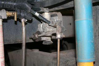
The ride height valves are located on the chassis suspension. One ride height control valve is located on the front steer axle. The body of the valve is mounted to the center of the mainframe with a link rod attached to the lower “H” frame. The other two (2) ride height valves are located on the rear outboard mainframe just inside the rear set of airbags for the drive axle. These valves also have a link rod attached to the lower “H” frame. The link rod is comprised of two rubber eyelets attached with small band clamps at each end of a steel vertical rod. The clamps can be loosened and vertical rod slid in or out of the eyelets to set proper ride height.
As the coach moves down the road the valves are continually adding or exhausting air from the airbags to maintain the ride height. The valves are designed to auto compensate for road variation, weight transfer and loads. They also have a dead band of about 3 degrees to compensate for “road jitter” as the suspension is moving over small bumps.
Note: The adjustment of these valves is very critical and it is recommended a qualified service technician check them at every service interval.
Accurate measurements can only be taken from the upper trailing arms for each axle.
This measurement is not as easy to obtain as measuring at each airbag. However, the measurement at the bags is not as accurate, but by averaging the measurements of the bags and a little common sense proper ride height can be obtained.
Measure the rear set of bags for the front and rear axles. Measuring from any other location (i.e.; body components like wheel well skirts or body panels) may not accurately reflect measurements relative to the chassis. The proper measurement band between “top of bottom plate” to “bottom of top plate” Said another way it is the distance occupied by the airbag (airbags only) is 8″(+ or- 1/4″) front and rear.
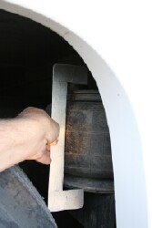
Ride Height Valve
A small stick of wood such as a 1″ X 1″ can be cut to the proper length for gauging (it’s easier than trying to hold a tape measure). You must park the coach on a level surface and start the engine and allow the chassis air supply to fill up and then exhaust. Make sure the HWH level system is in the travel mode. Leave the engine running while adjustments are made to maintain system air pressure. Always begin your adjustments with the rear, because the two valves on the rear maintain proper height side to side. Once you have set the rear then you adjust the front valve. Sometimes adjusting this valve can be tricky because of the fact you have only one valve, and some amount of differing weight distribution, it can be difficult to get both sides perfectly equal, but they should be very close within the adjustment band.
The 8″ measurement is between the mounting plates that are welded to the frame members. If you want to include the plates in the measurement just add 1/2 inch as each plate is 1/4 inch thick. The rounded metal at the top of each air spring/bag and the curved thing (called a piston) at the bottom is considered part of the air spring for measurement purposes. The fore and aft springs/bags at each axle corner operate as pairs. If one of a pair is more than 8″ the other should be an equal amount less. The front can be this way also side to side if the coach is not on a flat surface when the measurement is taken (assuming the rear sides are equal height). If the ride height needs to be increased, the distance between the clamps on the rod needs to be increased. Be sure the ends of the rod are under a clamp when finished and not just stuck in the rubber.
It is a good idea before every trip to make visual inspection around your coach for proper ride height and always be aware of how your coach is riding and driving. If you see that there is a problem contact your nearest Foretravel dealership to schedule an appointment.
—————————————————————————————————————-
When you level while parked, the leveling system tries to level the coach for the comfort of people, refrigerators, water in containers, etc. While in motion, the leveling system tries to keep the chassis at a constant height above the axles.
When traveling, the ride height (leveling while traveling) will be controlled by the ride height valves. There are two in the back and one in front. It is easy to see the mechanisms in the back. Look in the access doors for the batteries and isolator. The ride height controllers are the valves and mounts that look like a big Tinker Toy structures with one rod connected to the chassis and the other connected to the H frame (the frame for the axles and wheels). The valves attempt to keep the distance between the H frame and the chassis at 8″ when the coach is in travel mode. When the coach goes around a turn, the chassis will lean outward, compressing the airbags on the outside of the turn and expanding the airbags on the inside of the turn. The ride height valves will attempt to correct by exhausting air from the expanded bags and adding air to the compressed bags. On the next turn in the opposite direction, the valves will again exhaust air from bags on the inside of the turn and add air to bags on the outside of the turn.
Changes in attitude from front to back because of bumps and attitude changes will cause adjustments. It is a dynamic adjustment system with the purpose of keeping the distance between chassis and H frames constant. In travel mode, “level” means that the chassis is the proper height above the H frames. When parked, “level” means the egg won’t roll off the countertop while you get out of the other ingredients. There are valves and controls for each purpose. J D Stevens 1997 U295 36′
How Foretravel did air leveling before HWH.
Here is how it works and it’s quite ingenious (kudos to CM Fore or whoever invented it):
Each of the three ride height valves (mentioned above) is mounted on a small pivot plate that rotates the whole ride height valve. Connected to the plate is a large sheathed cable (like the kind you see on boat steering) that rotates the entire ride height valve. When this is done it “tricks” the valve into thinking it needs to add or subtract air from the air springs.
The cables lead to 3 mechanical levers on the floor between the driver’s seat and wall:
Left for the left rear. The middle for the front axle. Right for right rear. Example: Push the middle lever forward = front drops down proportionally.
The brain of the system is between your ears: read the bubble, move
the lever.
Once the coach is level, it will stay that way as long as there is system air.
The levers have a center detent (with microswitches) to illuminate the dash “air level” light. The light goes out = travel position.
Yes, it does take an extra minute to make adjustments. My coach has a 120VAC 3/4hp air compressor to keep the system pressure up. I put a timer on it so it doesn’t start in the middle of the night.
But think of it: No electronics. No sensors. No extra air valves. Not even any extra airline connections. Elegantly simple and reliable. John Fitzgerald 1991 U300 40′