by Barry and Cindy 1997 U270 36′ 2/25/11
Outside step and inside step slide cover are moved with dual-action pneumatic cylinders. Cylinders are controlled with 3-way pneumatic 12-volt valves located on the outside back of the bottom step. There are separate valves for inside slide and outside step. Each valve has an input air line and output adjustable exhaust port.
Two other air lines on the valve go to either end of the cylinder to either extend or collapse cylinder. 12-volts move inside of the valve to force air to one end of the cylinder. Removing 12-volts allows inside of the valve to spring return to force air to another end of the cylinder. When one air line is pressurized, the other air line is exhausted to the exhaust port. The exhaust port is adjustable to the slow return of the cylinder to prevent slamming in either direction. Removing and cleaning the exhaust port can improve actions.
You could put your own 12-volts to a valve to see if parts move. The valve is easily disassembled to clean and get a sticking valve to move freely.
Some have a step switch to the right of the driver’s knee on the center console. Switches are usually under a cover to prevent accidental movement. I don’t think there are stoplights, so your step switch could operate the step slide pneumatic valve.
If you have two switches to operate step slide, each switch is a 3-wire single-pole double-throw. One switch has 12-volts to the center pole. Another switch has a center wired to the pneumatic valve. The top & bottom poles are wired to each other, so either switch will close or open 12-volts to the valve.
The outside step is powered by ignition through the door magnetic reed switch. When the ignition is on and the door closed, 12-volts is supplied to step pneumatic valve. The opening door or turning off ignition allows the valve to spring return. Some have a modified circuit to allow step to also close when the ignition is off and the door closed.
The following is how the two pneumatic air valves that control the step cover and outside step work on our 1997 coach:
Both valves are the same part number but work independently. Some coach owners have repaired a leaking valve by successfully taken apart their valve, cleaned it and put it back together. Later coaches used a different valve than we originally had on our coach, so I purchased & installed the new valve: www.Norgran.com Part # V12R517AB312B $60, description = Valve, solenoid-operated, spring return, 12 volt DC.
Nathan Cutsforth the Norgren Express Sales Representative 720-283-5549 says that V61R517AA312JB is the replacement valve $65.70/each
The new style valve had to mount slightly different than the original valve because it was physically longer than the original. Air from the front air tank is plumbed to the two valves mounted on the back outside of the step. Air pressure is reduced with a small adjustable regulator. One for each valve. An air pressure gauge shows set PSI. Our regulator’s adjustment would not turn because the regulator adjustment shaft had corroded, so I left it at the set pressure.
Valve has four ports:
1) input from the regulated air supply.
2) output with a filtered adjustable airflow screwed on.
3) connected to one end of the air cylinder.
4) connected to the other end of the air cylinder.
Valve has two positions:
A) solenoid is energized with 12 volts. Air flows from port #1 (air supply) TO port #3 (cylinder end). Air flows from port #4 (another end of the cylinder) TO port #2 (slowly dump air to atmosphere). Close step cover/raise step.
B) solenoid is returned to a relaxed position by an internal spring when 12 volts is turned off. Air flows from port #1 (air supply) TO port #4 (other end of the cylinder). Air flows from port #3 (cylinder end) TO port #2 (slowly dump air to atmosphere). Open step cover / lower step.
To prevent the step cover slamming open or slamming closed, a screwed-in adjustable exhaust port is partly closed down to restrict how fast air can leave the cylinder. This restriction in effect controls how fast new air can come into the other end of the cylinder and how fast the cylinder can move from open to close or close to open. This exhaust port can be removed from the valve and cleaned. It has a brass filter to keep debris from entering the valve. Whenever the coach has air pressure, the step or step slide is continuously being held open or closed by air pressure, so we cannot manually move them.
This is true if the ignition is on or off. When all system air pressure is depleted, the step and step slide can be manually opened or closed. Our step slide has one air cylinder. The step has two air cylinders working together. Hope this paints a picture for the mind on how these things work.
——————————————————————————————————————-
An additional comment on the pneumatic step cover:
The step cover solenoid valve on our 1999 U270 started leaking air. Enough that it was showing a pressure differential in the brake system. Replacing the solenoid valve didn’t stop the leak. Finally, we discovered the air cylinder was leaking air past the piston, and the valve was passing the air out the exhaust side.
The air cylinder is in a very tough place to access. The techs at Foretravel said it was a job they would not attempt in the field, and it was difficult to even in their shop. In desperation, we tried pumping grease into the lines going to both sides of the cylinder. It worked like a charm! And blew the excess grease out the valve exhaust. It’s been almost a year, still no leak. And now I have a spare solenoid valve. Ed Kipling 1999 U270
I had to replace a rotted front entry step and riser. The thin pan underneath the step was also corroded through in places. Removing the fiberglass box made repair much easier. It allowed me to slide the new HDPE step all the way under the threshold and be supported by sitting on the box beam and being screwed to the bottom of the new riser. Then I added a piece of epoxy coated exterior plywood underneath the HDPE and fastened it to the box beam, the rest of the plywood box structure and the HDPE. I could not have done this with the box in place. Fortunately, removal and replacement of the box are pretty simple.
Thanks to MAZ and others who have done this before me for their descriptions and pictures. Here is a recent picture of the whole assembly from my 1999 U320
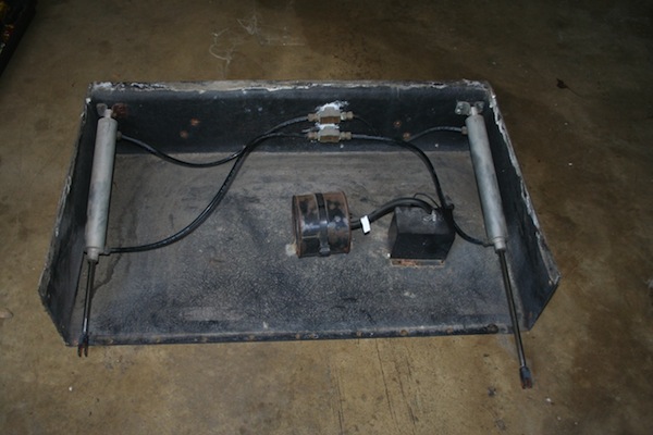
ARO Economair 2418-1089-080 and some other unnecessary numbers. The numbers indicate that this is a round cushioned cylinder (24) that has a 1-1/8″ bore size (18), it is double-acting with a rear tang (-1), with a nitrile O-ring (0) and a 303 stainless rod (89) and a stroke length of 8″ (-080)
It is a simple job to remove and take apart. Drill out the rivets holding it to coach then once off carefully pry around the metal edge and fiberglass outer step cover to be able to see and get to the framework. A hard caulk ?? was used when built but it does come apart. Once you get to that stage I am sure the inside will be a mass of rust etc and you can either take it to get sandblasted or grind and scrape as much off as possible.
Once this is done you should coat it with Phosphoric acid (POR 15 or similar) to seal and control the rust. This can be painted once dry. I drilled 4 –1/4″ holes in the bottom flange of step frame so that in the up position any water that gets in will drain out the bottom. I also drilled a 1/8th inch hole in fiberglass cover to align with these holes in the frame again so any water runs out. I used a Polyurethane caulk when putting the cover of a step back on.
It is then refastened to hinge with pop rivets or? The bend on the threaded rod can be straightened but the shaft will need to be supported so it is not bent. Easy job just time getting it rust-free.
The cylinders are held into the back wall of “box” with 4– small bolts. Just lie under and you will see the nuts you need to take off then the cylinder just pulls out the front with an air line. They are pressed into the fitting by a quick connect ring so just push the end of fitting in and the line will come out by pulling lightly. The little bolts are a b–ch to get back in place as it is awkward so I tack welded them to the bracket they go thru so It was easy to locate in the back of the box and I did not need to hold a screwdriver on them to run the nuts on the back.
The only way it will leak air is if the scratch is exactly where it stops on both direction ie: near the end of the stroke. You may be lucky!!! This really is an easy job to do but can be messy. Do not put it back together without drilling those drain holes or you will be doing it all again in a few years. John Haygarth 2000 U295 36′
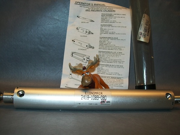
ARO Economair 2418-1089-080 and some other unnecessary numbers. The numbers indicate that this is a round cushioned cylinder (24) that has a 1-1/8″ bore size (18), it is double-acting with a rear tang(-1), with a nitrile O-ring (0) and a 303 stainless rod (89) and a stroke length of 8″ (-080) Brad Slaughter 2002 U270 36′