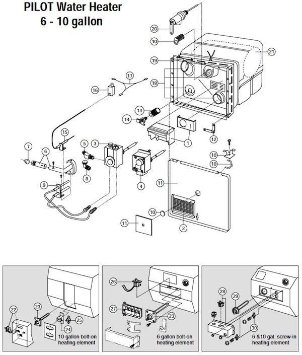
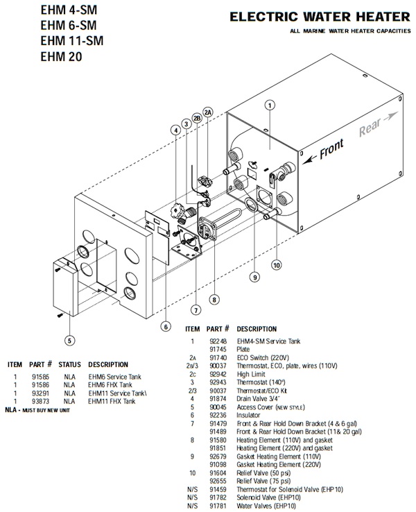
Atwood 6 and 10-gallon Electronic Ignition Water Heaters
Atwood water heaters are designed and approved for use only in recreation vehicles (travel trailers, 5th wheels, motor homes, etc.). They are offered in two sizes: 6 and 10-gallon capacities.
TYPE OF GAS IGNITION – This unit is ignited inside of the trailer by a remote ON/OFF switch. The water temperature is preset at 140° F.
EXPLANATION OF MODEL NUMBER:
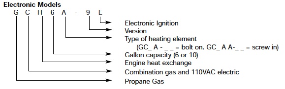
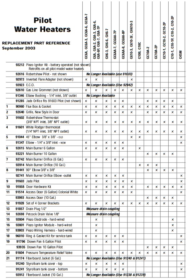
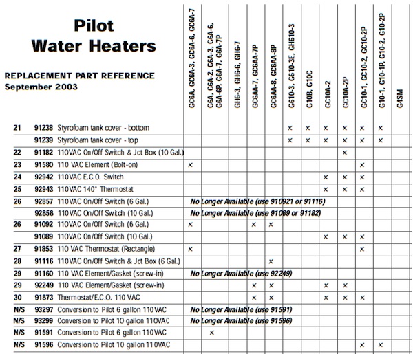
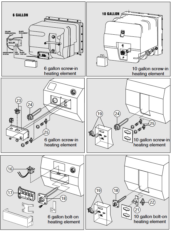
NOTE: When replacing the element on a combination gas/110 VAC unit, always check the back of the heater for the type of element it has. It will either be a bolt-on or screw-in element. They are not interchangeable.
FEATURES
• All units operate on propane gas.
• A pre-set thermostat set for 140° F. An aftermarket retro-fit adjustable thermostat is available and adjustable from 110° to 150° F.
• A heat exchange option is available. The water heater tank must have factory equipped heat exchange tubes welded on it already. They cannot be added later. A new water heater tank with this feature must be installed to use the heat exchanger.
• Skin mounting allows the water heater to be hooked up with plumbing and electrical before the sidewall is erected.
• This heater has a comparable, if not superior, anode type protection for the tank. The tank is manufactured with a clad aluminum lining that protects against corrosion but does not need to be replaced yearly as an anode rod. A more detailed explanation of cladding is found in the back of this manual.
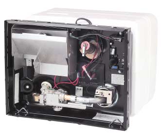
• 95% of all servicing is done on the outside of the water heater. 110 VAC heating components are the exception. Since they are located on the back of the water heater inside the trailer.
• A flush flange is available for all models. This makes the access door flush with the sidewall.
• There are multiple protection features in the form of a pressure-temperature relief valve, a limit switch in the gas thermostat and an externally sealed combustion chamber.
• Both the six and ten-gallon units have the lightest weight in the industry.
• On all trailers purchased after June 1, 1997, the Atwood Limited Warranty is for a period of two years. This includes all reasonable labor charges.
• We have 700+ Service Centers throughout the United States.
Recommended Tools and Equipment
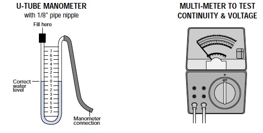
U-Tube Manometer – This is the most accurate device for measuring gas pressure. If you use a dial-type manometer, it should be calibrated periodically with this type of manometer. Multi-meter – This is the most versatile meter and will test continuity and 12VDC. These tests will allow one to verify voltage problems or faulty components. The entire electronic system can be tested with this meter.
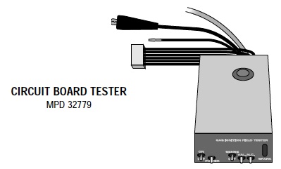
Circuit Board Tester – The tester is capable of testing any of the circuit boards (Fenwal and Channel models) that we have used on our water heaters. It is a simple tabletop device that will diagnose the following items on a circuit board: power circuit, sense circuit, spark generation, and the lock-out mode. For use on circuit boards with a flying lead connection, splice a wire into the black wire of the tester harness with a 1/4˝ male terminal on the free end.
Common Hand Tools – 1/8˝ and 1/4˝ nut drivers, open-end wrenches, flat blade, and Phillips screwdrivers.
Leak Test Solution – A solution that bubbles when applied to gas fittings or connections showing where a gas leak is present.
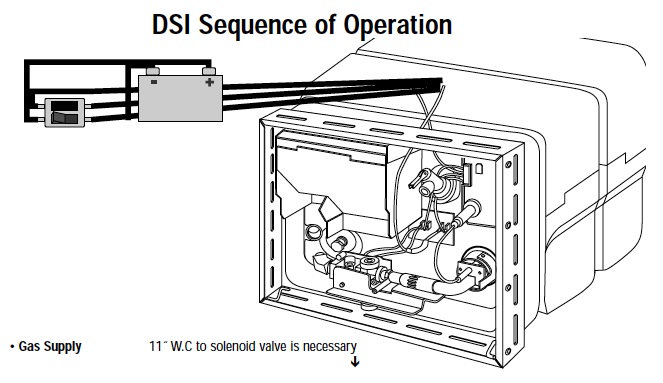
• 12VDC Battery or filtered side of Converter – Voltage source to the water heater
• ON/OFF Switch – It supplies 12VDC to the water heater
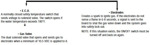
• Thermal Cut-Off – A one-shot heat-sensing fuse that’s normally closed and sends power to the thermostat. When tripped by excessive heat (190°F), (i.e. blocked burner or flue tube) it cuts power to the circuit board and shuts down ignition.
• Thermostat – A normally closed non-adjustable temperature switch that sends current to the circuit board. It opens when the water temperature reaches approximately 140°F.
• Circuit Board – The next step is the direct spark ignition system. For a period of 6-8 seconds, the circuit board will send voltage to both the gas solenoid valve and the electrodes. If ignition does not occur, the board goes into a lock-out condition and the non-ignition light illuminated at the ON/OFF switch.
WATER HEATER LOCKOUT – SPARK PRESENT BUT NO GAS
| CAUSE | SOLUTION |
| Gas pressure incorrect | Set inlet pressure at a minimum 11˝ W.C. with two or more gas appliances running |
| Low voltage | Correct power supply – 10.5 VDC minimum |
| Blocked main burner tube | Clean burner tube |
| Blocked main burner orifice | Clean or replace the orifice |
| Loose wires on E.C.O. | Secure wire connections |
| Loose wire connections on the solenoid valve | Secure wire connections |
| Loose valve wire on the wiring harness | Repair wire on edge connector or replace wiring circuit board harness |
| Defective E.C.O. | Replace E.C.O. |
| Defective circuit board | Replace circuit board |
| Defective solenoid valve | Replace coils or solenoid valve |
| No gas to the solenoid valve | Correct gas supply |
| Dirty connector on circuit board | Clean edge connector |
WATER HEATER LOCKOUT – GAS PRESENT BUT NO SPARK
| High tension lead wire loose | Secure wire connection on circuit board |
| Electrodes loosely attached to the main burner | Secure electrodes to the main burner |
| Improper electrode gapping | Re-position spark gap to 1/8˝ and into the path of the flame |
| Dirty electrodes | Clean electrodes |
| Wires loose in electrode porcelain | Replace electrodes |
| Cracked porcelain on the electrode | Replace electrodes |
| Defective circuit board | Replace circuit board |
WATER HEATER LOCKOUT – GAS AND SPARK PRESENT
| Gas pressure incorrect | Set inlet pressure at a minimum 11˝ W.C. with two or more gas appliances running |
| Low voltage | Correct power supply – 10.5 VDC minimum |
| Poor electrical ground | Secure electrical ground |
| Electrodes out of the flame pattern | Re-adjust electrodes Electrodes sparking to screw fastening burner to flue tube Adjust electrodes away from the screw |
| Dirty electrodes | Clean electrodes |
| Partial obstruction in the main burner | Clean main burner |
| Partially obstructed main burner orifice | Clean main burner orifice |
| replace Improper air adjustment | Adjust main burner air shutter approximately 1/4 open |
| Flame spreader on the main burner out of adjustment | Adjust flame spreader so that it is square to the end burner tube out of alignment of the main burner |
| Manifold not aligned with the main burner | Re-align solenoid valve with the main burner |
| Partially opening solenoid valve | Replace solenoid valve |
| Defective circuit board | Replace circuit board |
EXCESSIVE OR INSUFFICIENT WATER TEMPERATURES
| By-pass kit valves not set properly | Place valves in the proper position |
| Thermostat not seated against the tank | Reseat thermostat |
| Defective thermostat | Replace thermostat |
ERRATIC BURNER FLAME OR SOOTING
| Low gas pressure | Set inlet pressure at a minimum 11˝ W.C. with two or more gas appliances running |
| Poor gas supply | Replace gas supply |
| Improper air adjustment | Adjust main burner air shutter approximately 1/4 way open. The flame should be mainly blue and quiet. |
| Poor main burner alignment | Adjust valve and main burner alignment |
| Misaligned burner flame spreader | Align flame spreader so it is square with the end of the burner tube. |
| Blocked burner orifice | Clean orifice. DO NOT enlarge the orifice |
| Obstructed main burner | Clean main burner |
| Obstructed “U” tube | Clean “U” tube |
| Obstructed exhaust grille | Remove obstruction |
NO SPARK AND NO GAS
| No voltage | Correct power supply – minimum 10.5 VDC |
| The dirty edge connector on circuit board | Clean edge connector |
| Defective thermal cut-off | Replace thermal cut-off |
| Defective ON/OFF switch | Replace switch |
| Defective circuit board- | Replace circuit board |
| Defective thermostat | Replace thermostat |
1. CHECK ALL OF THE WIRE CONNECTIONS.
Poor or corroded wire connections cause most of the intermittent problems in water heaters. You should go through and pull all of the wires off any spade connections. Then reconnect them and ensure the connections are tight and corrosion-free.
We want to point out two connections often overlooked.
First, check the (green) ground wire of the circuit board. This wire screws down under the circuit board mounting screw. If that screw for the board is loose, you may not have a secure ground.
Second, check the four-wire edge connector going into the circuit board. Remove the circuit board. Take a pencil eraser and clean the marks off the connection of the circuit board. Reconnect the four-wire edge connector onto the circuit board and then immediately remove it. Look at the edge connector of the board. You need to see four good scratches in the connection. If you do not see four scratches, then you will need to repair the edge connector or replace the wire harness.
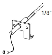
2. CHECK THE INTEGRITY AND POSITION OF THE SPARK PROBE ASSEMBLY.
The gap between the sparking probe and the ground probe should be 1/8 inch. The probes should be clean and free of cracks, flaking, and corrosion. Position the probes so that they are in the path of the gas flow. Cracks in the ceramic insulator can also be the source of an intermittent problem. To check for cracks insert a fiber washer or any other type of insulation material in the 1/8” gap between the rods. Remove the gas valve from the circuit and turn the unit on. If you see a spark jumping from the ceramic to the ground rod or bracket, replace the spark probe.
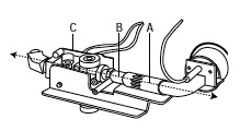
3. CHECK THE ALIGNMENT OF THE MAIN BURNER TO THE ORIFICE.
Position the main burner tube (A) so that the gas coming out of the orifice (B) is going straight down the middle of the burner tube. If the alignment is off, the gas will bounce down the tube which will alter the gas flow once it reaches the spark. Manually shift the valve (C) with your hands to achieve this alignment.
4. CHECK THE ALIGNMENT OF THE FLAME SPREADER ON THE BURNER TUBE.
At the end of the burner tube, there is a dime-shaped deflector disk. This disk spreads the flame out for proper heat distribution. Align the flame spreader (A) so that it is parallel to the end of the tube and positioned in the center of the end of the tube. If the flame spreader is out of position, it could divert the gas away from the spark and cause intermittent ignition.
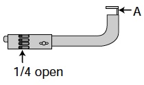
5. CHECK THE AIR ADJUSTMENT.
The burner tube has an adjustable air shutter on it at the end where it goes over the orifice. Position the air shutter so that it is 1/4 of the way open. We are looking for a blue flame with small traces of yellow in the flame. If the flame is fairly quiet then it is adjusted correctly.
6. CHECK THE CLEANLINESS OF THE ORIFICE.
The orifice is the hex head brass fitting that is screwed onto the brass manifold of the valve. You will have access to this part once the burner has been removed. Remove the brass orifice and clean it with isopropyl alcohol. NEVER enlarge the size of the orifice.
7. CHECK FOR OBSTRUCTIONS IN THE MAIN BURNER TUBE.
The cleanliness of this tube is very important. Spider webs, soot, and other debris can accumulate, causing problems with the gas flow down the tube. We recommend cleaning the burner tube with a brush and not compressed air. Compressed air may not fully remove the obstruction.
8. CHECK THE CLEANLINESS OF THE FLUE TUBE.
The flue tube is the 2-1/2 inch diameter tube that starts at the bottom right corner of the water heater (where the main burner flame enters) and comes out the top left. This tube can become blocked by debris like insect nests or soot. To clean remove the metal flue box in the top left corner of the water heater. To facilitate cleaning unfold a wire hanger, wrap a rag around the end and use this to swab out the tube.
9. CHECK THE VOLTAGE TO THE VALVE.
Make sure that the voltage to the gas solenoid valve is between 10.5 and 13.5 volts DC. Voltage drops can occur at almost any component. Turn on another twelve-volt appliance when you check the voltage so that you can see how the converter is working with a load. The voltage itself can be intermittent. With linear converters, the 12 VDC varies depending on the 115 VAC. If the 115 VAC is high then the 12 VDC will be high, and if the 115 VAC is low then the 12 VDC will below. If the power to the water heater is connected to the unfiltered side of the converter, move it to the filtered side.
10. CHECK THE GAS PRESSURE OF THE RV.
Make sure the gas pressure of the RV is checked with preferably the furnace and the range on to simulate a load. The pressure should be an 11-inch water column under load. Besides gas pressure being at the proper level, there are other strange things that can happen inside gas lines that cause intermittent problems. We have seen oil build up in a gas line that meant there was good pressure to one appliance but not the correct pressure to another appliance. Moisture could also build up in the gas line that would freeze and partially block the line. Intermittent pressure from the regulator of the bottles is still another area that should be investigated.
11. INTERMITTENT CIRCUIT BOARD. If you have gone through all of the above checks and the intermittent problem is still occurring, only then check the circuit board. Ensure the circuit board is clean and reasonably moisture-free before you change it. There are two major points that should have stood out to you from this list. First, the majority of intermittent ignition problems on Atwood electronic ignition water heaters can be corrected by cleaning certain components or making simple adjustments. Second, ignition problems can be found in other components than the circuit board. The circuit board is not the end-all solution to ignition problems. This mindset developed a number of years ago with the introduction of the first circuit boards that were not very reliable. We’ve learned a lot since then. Technology has progressed making today’s circuit boards very reliable. The circuit board can only do what the other components of the water heater allow it to do.
**POTTED CHANNEL CIRCUIT BOARDS
Atwood **potted circuit boards can be tested using a multi-meter. This test must be performed with the circuit board removed, and the meter set to the ohms scale. This will check the continuity of all tracks on the harness connection of the board. The following steps should be used to test each track.
A. Cross leads of the meter to ensure it is registering continuity.
B. TO TEST POWER TRACK: Place negative lead of the multimeter to the ground (green wire) track of edge connection and the positive lead of the multi-meter to top power (brown wire) track of edge connection. If no continuity, the board is defective. *Atwood does not warranty this installation related failure.
C. TO TEST LAMP TRACK: Place negative lead of the multimeter to the ground (green wire) track of edge connection and the positive lead of the multi-meter to lamp (blue wire) track of edge connection. If no continuity, this indicates a blown lamp track. Circuit board will still fire unit but lamp light will not come on. This is caused by a short in the blue wire between the unit and the switch. Wiring must be corrected before the board is replaced. *Atwood does not warranty this installation related failure.
D. TO TEST VALVE TRACK: Place negative lead of the multimeter to ground (green wire) track of edge connection and the positive lead of the multi-meter to valve (red wire) track of edge connection. If no continuity, this indicates a blown valve track.
- If the valve wire is shorting under the flue box – Atwood will warranty the board.
- If the E.C.O. terminals are contacting the drawn pan – Atwood will warranty the board only if the inner tank of the water heater was installed flush on the floor of the coach.
- If the inner tank of the water heater does not rest flush against the floor of the coach – Atwood does not warranty this installation related failure.
* Installation related failures on circuit boards are the responsibility of the coach manufacturer.
** Nonpotted circuit boards can be checked by turning the board over and visually inspecting each track for a burn mark or break in the track itself. A burn mark or broken track indicates the board is blown. Depending on which track is blown determines whether it is covered under Atwood’s warranty as stated in section B, C, and D.
THERMAL CUT-OFF DEVICE Current Atwood direct ignition water heaters are equipped with a thermal cut-off device. This device is located on the incoming power wire and is connected to the thermostat. The thermal cut-off is designed to permanently break the circuit and shut down the water heater before excessive heat can cause damage due to obstructions in the main burner tube or flue tube caused by spiders or mud wasps. These obstructions can cause the main burner flame to burn outside the main burner tube. When the flame or the heat from the flame contacts the thermal cut-off, the circuit will open.
If there is no heat damage to the thermal cut-off, and if it is determined defective, Atwood will cover the replacement of this device under warranty. We will allow .25 hour at your Atwood approved warranty rate. If there is heat damage the device performed its safety feature and no warranty labor will be allowed. Any obstructions should be removed, alignment checked and gas pressure was taken before a new thermal cut-off is installed.
Note: When replacing a thermal cut-off, also examine the grill in the access door while the door is in the closed position. The wide aluminum band of the grill should be at the bottom. If it is at the top, this condition may trap exhaust heat and possibly also cause thermal cutoff to trip. To correct, remove the grill from the door and snap back in place with the wide aluminum band at the bottom.
THERMOSTAT
The thermostat on this water heater is pre-set at 140° F. The water heater will cycle off when the water temperature reaches 140° F. and will generally take 20-25 minutes to reach this temperature. It will cycle back on when the water temperature cools down to approximately 115° F. In the latter part of the heating cycle though, it is very common for the pressure-temperature relief valve to weep. Refer to the page covering weeping relief valves to remedy this situation.
If a customer is dissatisfied with the temperature of the water, first check the water temperature with a cooking thermometer and verifying that the initial cycle is within the time noted above. If not, an adjustable thermostat may be purchased allowing the water temperatures to be adjusted from 110 – 150° F. It fits in place of the original thermostat.
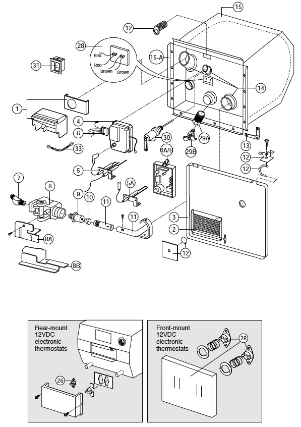
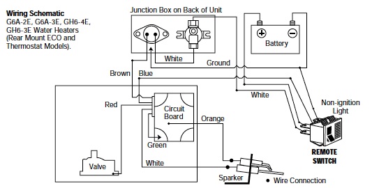
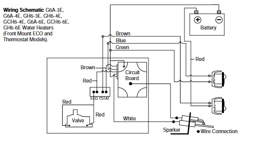
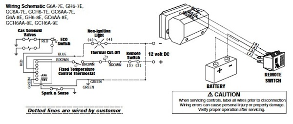
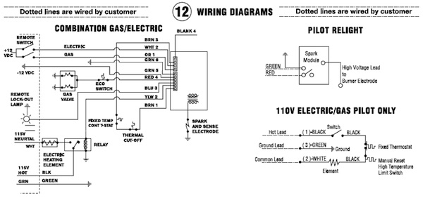
Water Heater Wiring Schematics
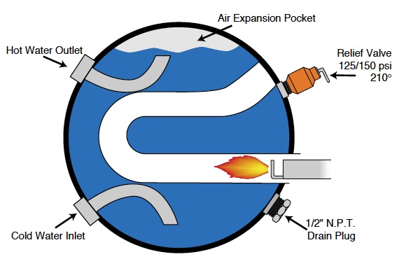
PRESSURE-TEMPERATURE RELIEF VALVE
Weeping or dripping of a pressure-temperature relief valve while the water heater is running DOES NOT mean it is defective. This is a normal expansion of water as it is heated in the closed water system of a recreation vehicle. The Atwood water heater tank is designed with an internal air gap at the top of the tank to reduce the possibility of weeping and dripping. In time, the expanding water will absorb this air. To replace the air follow these steps:
Step 1: Turn off the water heater
Step 2: Turn off the incoming water supply
Step 3: Open the closest hot water faucet in the coach Step
4: Pull the handle of pressure-temperature relief valve straight out and allow water to flow until it stops. Step
5: Allow pressure-temperature relief valve to snap shut, turn on water supply and close faucet
WATER HEATER TANK CORROSION
Pinhole leaks from galvanic corrosion may cause the water heater tank to fail.
Microscopic particles of metals (like iron and copper) suspended in water, set up a reaction inside the water heater that is not unlike the principle on which an automotive battery operates. The aluminum tank is the anode and the metals in the water serve as the cathode. Consequently, the aluminum gradually sacrifices itself and aluminum particles are carried away with the water flow.
A white scaly material (aluminum oxide) often is formed around the points where the heaviest action is taking place and heat accelerates the process. The severity of the problem varies considerably in different locales depending on the metal and mineral content of the water. White deposits inside the water heater tank are usually from water impurities that have settled out.
Periodic flushing of the water heater tank under pressure is recommended to slow down this process. For flushing instructions see your owner’s manual or contact Atwood for a copy of our recommended procedure.
ATWOOD CLAD TANK The Atwood water heater tank is constructed of a core of high strength aluminum. The interior of the tank consists of a 15% thickness of type 7072 aluminum (pure aluminum and zinc) that is fused to the core during the rolling process. This material protects the tank from the effects of heavy metals and salts found in waters throughout the country. It is anodic to these heavy metals and acts much like an anode in a steel glass-lined tank except it will last much longer. There is also no need to replace an anode on a yearly basis.
Flushing the tank on a regular basis has been found to be helpful in ensuring the best performance of your water heater and adding to the useful life of the tank. For flushing instructions see your owner’s manual or contact Atwood for a copy of our recommended procedures.
FLUSHING YOUR WATER HEATER TO REMOVE THE ROTTEN EGG ODOR
1. Turn off your main water supply. Drain your water heater tank. Reinstall drain plug. Remove the pressure-temperature relief valve. With a funnel use 4 parts white vinegar to two parts water. (In a 6-gallon tank that would be 4 gallons vinegar to 2 gallons water).
2. Cycle the water heater, letting it run under normal operation 4-5 times. At no time do you remove the vinegar from the tank Once this has been completed, remove the drain plug and drain the water heater.
3. After thoroughly draining the tank, to remove the sediment, flush the water heater.
- If you elect to use air pressure, it may be applied either through the inlet or outlet on the rear of the tank or applied through the pressure-temperature relief valve. Remove the pressure-temperature relief valve and insert your air pressure through the pressure-temperature relief valve coupling. In either case, with the drain valve open, the air pressure will force the remaining water out of the unit.
- If air pressure is unavailable, your unit can be flushed with fresh water. Freshwater should be pumped into the tank either with the onboard pump or external water pressure. External pressure may be hosed into the unit either through the inlet or outlet found on the rear of the tank or the pressure-temperature relief valve coupling located on the front of the unit.
- Continue this flushing process for approximately five minutes allowing ample time for the freshwater to agitate the stagnant water on the bottom of the tank and forcing the deposits through the drain opening.
4. Upon completion of the steps above, replace the drain plug and the pressure-temperature relief valve.
5. Refill tank with freshwater that contains no sulfur. The Atwood water heater is designed for use in a Recreation Vehicle. If you use your vehicle frequently or for long periods of time, flushing the water heater several times a year will prolong the life of the storage tank.
WINTERIZING INSTRUCTIONS
1. Turn off your main water supply, that is, your pump or your water hook up source.
2. Drain your water heater inner tank. Upon doing so, you will note that, due to the location of the drain plug, approximately two quarts of water will remain in the bottom of the tank. This water contains most of the harmful corrosive particles. If while draining the unit, you note that it is flowing sporadically or trickling, instead of flowing steadily, we recommend one of two things. You should first open your relief valve to allow air into the tank and secondly, take a small gauge wire or coat hanger device and prod through the drain opening to eliminate any obstructions.
3. After thoroughly draining the tank, you should then flush it with air pressure or freshwater. If you elect to use air pressure, it may be applied either through the inlet or outlet on the rear of the tank. It may also be applied through the relief valve part. In this case, it will be necessary to first remove the relief valve support flange. In either case, with the drain valve open, the air pressure will force the remaining water, along with the corrosive particles, out of the unit. However, if air pressure is unavailable, your unit can be flushed with fresh water. Freshwater should be pumped into the tank either with the assistance of the on-board pump or with the assistance of external water either through the inlet or outlet found on the rear of the relief valve coupling located on the front of the unit. Continue this flushing process for approximately five minutes allowing ample time for the freshwater to agitate the stagnant water on the bottom of the tank and thus forcing the deposits through the drain opening.
4. Upon completion of the steps above, replace the drain plug and the pressure-temperature relief valve.
5. After this procedure, there will be approximately two quarts of water left at the bottom of the inner tank. Should this water freeze it will not cause any splitting of the tank.