by Brad Slaughter 2002 U270 36′ 6/27/13
Precaution: Remove both wires from the circuit breaker (one was a forked wire to A1 and 1 of the relay, the other went to the bathroom switch via a 2-wire loom) You will note that the original installation has ALL of the pump’s current draw going from the circuit breaker, through this wire, all the way to the bathroom.
ALL the current went through this switch and then headed back down to the bus area where a butt connector was used to connect it to a wire that went across the coach and down into the pump. I’m a lot more confident in the new arrangement that has the actual pump current going from the circuit breaker to the relay and directly to the pump. The only currents running to the bathroom and kitchen now are the minimal current used to briefly pulse the relay, as well as whatever small amount, is necessary to keep the indicator lights lit. This circuitry is exactly how the U320 is wired.
Switch 1 preparation
Remove both white wires from the bathroom switch.
Install a new MOMENTARY switch to the white wire that does NOT have the light wired to it.
On the other side of the new switch, place a new ground wire (to the ground bundle in this area).
Leave the other connector, with the light wire alone (tape it off). It is connected only to light, as the other end of the light is grounded already.
Switch 2 (or more) preparation
Run a pair of wires from the basement power bus area to the location of the new switch.
Use one wire from the bus area to connect to one side of a new MOMENTARY switch.
Ground the other side of the new switch with a new ground wire and the negative side of a new 12-volt indicator LED (if desired).
Connect the second new wire to the positive side of the LED.
Relay installation
As noted above, both wires should have been removed from the circuit breaker before starting for safety.
Connect the single switch wire you found on the circuit breaker onto A2 on the relay. It again serves as the switch wire, but now it will serve to momentarily impulse the relay only instead of carrying the circuit power to a switch.
Place the correct new switch 2 wire onto A2 also, for the new, second momentary switch.
Break the splice of the two wires you find spliced together with a butt connector. One wire goes directly to the pump (it winds to the left and up through the circuit breakers), and the other wire goes up into the 2-wire loom now just to the indicator light in the bathroom. It is what used to carry the current from the switch and on to the pump.
Now add another short wire to the two that were spliced together and connect it to terminal 2 on the relay. Pump and indicator lights are now powered from there. Connect the second (or more) indicator light to 2.
LAST ITEM to connect: Reinstall the double (forked) wire from the circuit breaker to A1 and 1 to the power circuit.
Press either switch momentarily and the pump will be energized, as well as both lights. Press again, both lights go out and the pump is off. There is no limitation on the number of switches that can be added.
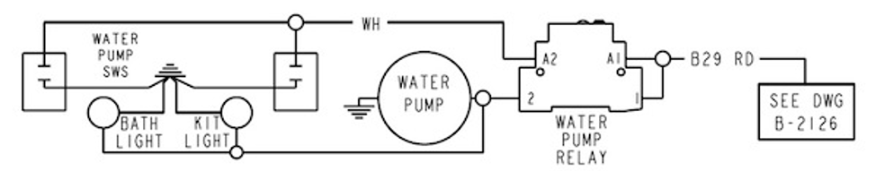
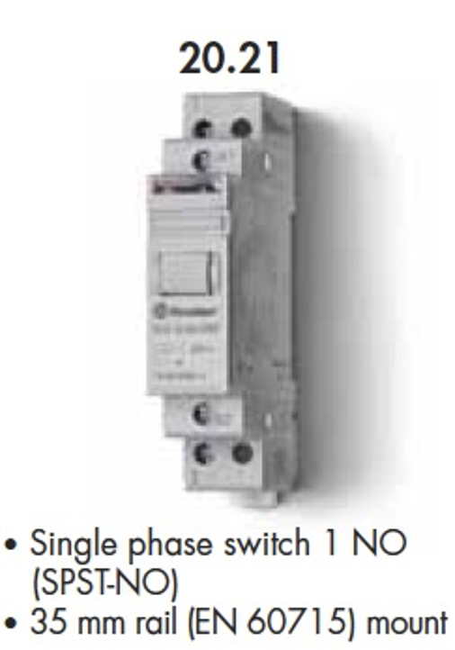
The drawing below reflects the use of a Finder 20.21 Impulse Relay that Foretravel used in 2002.
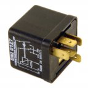
You may also use a different impulse relay, and a Volkswagen Headlight relay is a common choice. That part number is DNI 0127 or NAPA Echlin AR284 or 111 941 583. It has 5 terminals. Terminal 30 corresponds with A1. Terminal S corresponds with A2. Terminal 56 corresponds with 1 and since there are 5 terminals, 56a OR 56b corresponds with 2. Use either one or the other as the relay pulses back and forth.