GENERAL
If, after completing the routine operation and leakage tests, it has been determined that one or more components of the air dryer requires replacement or maintenance, refer to the following list to find the appropriate kit(s).
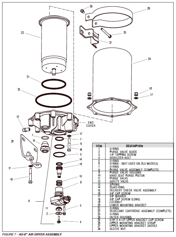
When rebuilding or replacing components of the air dryer use only genuine Bendix parts. For ease in servicing the AD-9™ air dryer desiccant cartridge assembly, it is recommended that the air dryer be removed from the vehicle.
MAINTENANCE KITS AVAILABLE:
5005037 Hard Seat Purge Valve Housing Maintenance Kit
5005893 Soft Seat Purge Valve Housing Maintenance Kit
These kits contain the parts necessary to rebuild the air portion of the purge valve housing and do not include the heater and thermostat.
107796 Remanufactured Desiccant Cartridge Replacement Kit
This kit contains the parts necessary to change the desiccant cartridge only.
107794 Desiccant Cartridge Replacement Kit
This kit contains the parts necessary to change the desiccant cartridge only.
107799 End Cover Check Valve Assembly Replacement 3/4 inch thread size.
107800 End Cover Check Valve Assembly Replacement 1/2 inch thread size.
800405 Service New Purge Valve Housing Assembly –
Soft Seat (w/heater and thermo.) 12-volt system.
5004341 Remanufactured Exchange Purge Valve
Housing Assembly – Soft Seat (w/heater and thermo.) 12-volt system.
5004479 Service New Purge Valve Housing Assembly -Hard Seat
(w/heater and thermo.) 12-volt system.
5004339 Service New Purge Valve Housing Assembly -DLU (w/heater and thermo.) 12-volt system.
5004338 Service New Purge Valve Housing Assembly – Soft Seat (w/heater and thermo.) 24-volt system.
5004342 Remanufactured Exchange Purge Valve Housing Assembly – Soft Seat (w/heater and thermo.) 24-volt system.
5004480 Service New Valve Housing Assembly – Hard Seat (w/heater and thermo.) 24-volt system.
5004340 Service New Purge Valve Housing Assembly – DLU (w/heater and thermo.) 24-volt system.
107695 Complete Mounting Bracket Kit
This kit contains the upper and lower brackets as well as the necessary hardware items to mount them.
GENERAL SAFETY GUIDELINES
WARNING! PLEASE READ AND FOLLOW THESE INSTRUCTIONS TO AVOID PERSONAL INJURY OR DEATH:
When working on or around a vehicle, the following general precautions should be observed at all times.
1. Park the vehicle on a level surface, apply the parking brakes, and always block the wheels. Always wear safety glasses.
2. Stop the engine and remove ignition key when working under or around the vehicle. When working in the engine compartment, the engine should be shut off and the ignition key should be removed. Where circumstances require that the engine be in operation, EXTREME CAUTION should be used to prevent personal injury resulting from contact with moving, rotating, leaking, heated or electrically charged components.
3. Do not attempt to install, remove, disassemble or assemble a component until you have read and thoroughly understand the recommended procedures. Use only the proper tools and observe all precautions pertaining to use of those tools.
4. If the work is being performed on the vehicle’s air brake system, or any auxiliary pressurized air systems, make certain to drain the air pressure from all reservoirs before beginning ANY work on the vehicle. If the vehicle is equipped with an AD-IS® air dryer system or a dryer reservoir module, be sure to drain the purge reservoir.
WIRING THE HEATER/THERMOSTAT
1. Determine the vehicle’s electrical system voltage and make certain that the AD-9™ air dryer that is to be installed contains the same voltage heater. Use the AD-9™ air dryer part number to confirm the proper voltage.
The AD-9™ air dryer is available with either a 12 or 24-volt heater which uses 75 watts of power.
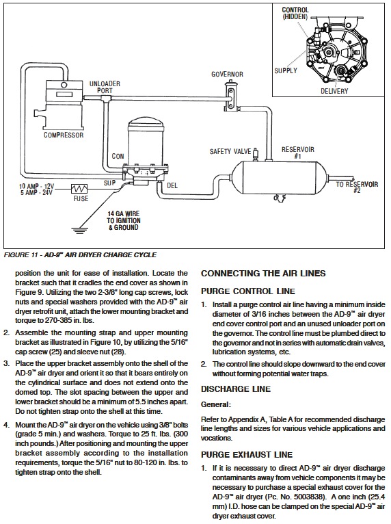
2. A two lead, 12 inches, wire harness with attached weather-resistant connector is supplied with all retrofit and replacement AD-9™ air dryers. Connect one of the two leads of the wire harness to the engine kill or ignition switch. The remaining leaders of the wire harness must be connected to a good vehicle ground (not to the air dryer or its mounting bracket). A fuse should be installed in the power carrying wire; install a 10 amp fuse for 12-volt heaters and a 5 amp fuse for a 24-volt heater.
3. Use 14 GA wire if it is necessary to lengthen the wire harness provided with the AD-9™ air dryer. Make certain all wire splices are waterproofed.
4. Tie wrap or support all electrical wire leading to the AD-9™ air dryer at 6 – 8-inch intervals. Note: Wires should have sufficient slack and not completely taught.
TESTING THE AD-9™ AIR DRYER
Before placing the vehicle in service, perform the following tests:
1. Close all reservoir drain cocks.
2. Build up system pressure to governor cut-out and note that the AD-9™ air dryer purges with an audible escape of air.
3. “Fan” the service brakes to reduce system air pressure to governor cut-in. Note that the system once again builds to full pressure and is followed by a purge at the AD-9™ air dryer exhaust.
4. It is recommended that the following items be tested for leakage to assure that the AD-9™ air dryer will not cycle excessively.
(A) Total air system leakage (See Bendix publication BW-5057 “Air Brake Handbook”).
(B) Compressor unloader mechanism.
(C) Governor.
(D) Drain cock and safety valve in the first (supply) reservoir.
(E) All air connections leading to and from the first (supply) reservoir.