by Leese Nevile
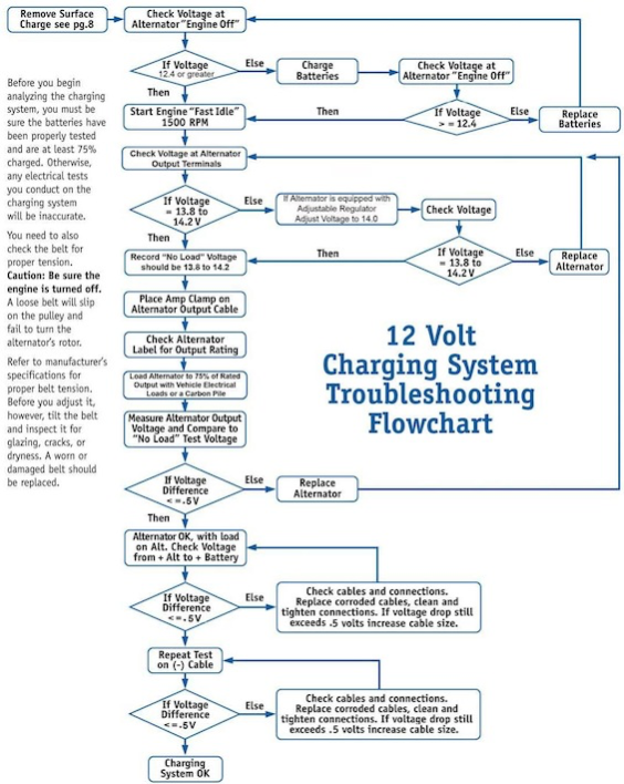
Before you begin analyzing the charging system, you must be sure the batteries have been properly tested and are at least 75% charged. Otherwise, any electrical tests you conduct on the charging system will be inaccurate. You need to also check the belt for proper tension. Caution: Be sure the engine is turned off. A loose belt will slip on the pulley and fail to turn the alternator’s rotor. Refer to the manufacturer’s specifications for proper belt tension. Before you adjust it, however, tilt the belt and inspect it for glazing, cracks, or dryness. A worn or damaged belt should be replaced.
Remove Surface Charge
A Step-By-Step Approach To Electrical Systems Problems
Finding problems in your vehicle’s electrical system doesn’t need to be a difficult process. By following the logical process of the investigation described in the service bulletin, you can track down and fix most of the commonly encountered electrical problems and particularly those related to the electrical system.
Step 1. Check the Battery Condition
A. Before beginning the battery test, make sure that the batteries are 95% – 100% charged. Use a battery charger, if necessary.
B. Shut off all electrical accessories in the vehicle and run the engine at approximately 1000 – 1200 RPM.
C. Connect a DC voltmeter to the battery terminals and measure the voltage. Compare the values to those specified by the battery manufacturer. If the voltage is above the manufacturer’s specification, an OVERCHARGE condition exists. If the measured voltage is below the manufacturer’s specification, a UNDERCHARGE condition exists.
Step 2. Overcharge and Undercharge Tests
Battery overcharge and undercharge conditions each require a specific set of procedures to be performed. The following diagram shows the order in which the procedures are performed. A more detailed description of these procedures follows.
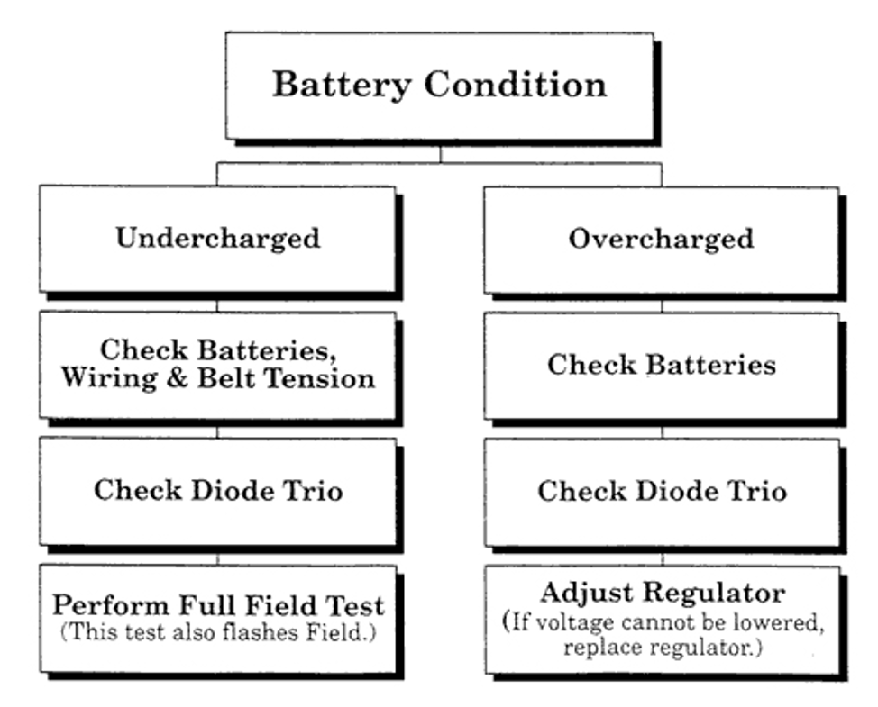
For OVERCHARGE Condition
Overcharge batteries (output over 14.2 volts for most 12-volt systems, or over 28.4 volts for 24-volt systems) can be caused by a defective battery (usually indicated by excessive gassing), a defective diode trio, or a defective or improperly adjusted voltage regulator.
After testing the batteries for shorts, perform the “Diode Trio Test” procedure in this bulletin, followed by the “Voltage Regulator Adjustment” procedure, if necessary.
For UNDERCHARGE Condition
To avoid unnecessary work, always check for loose belts, a defective battery, and damaged or corroded wires and connections first. If the battery, belts, and wiring are in good working condition, perform the “Diode Trio Test” procedure. If the diode trio is in good shape, perform the “Full Field Test.”
Diode Trio Test (on units equipped with a diode trio)
1. Remove the diode trio from the alternator.
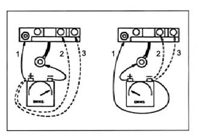
2. Connect the negative (-) ohmmeter test lead to the diode trio lead terminal as indicated in the diagram. Connect the positive (+) test lead to each of the three copper contact pads, one at a time. Observe the resistance at each contact pad and write down the resistance for each contact for later reference.
3. Reverse the leads so the positive (+) test lead is connected to the diode trio lead terminal and the negative (-) test lead connects to the contact pads. Again observe the resistance at each of the contact pads and record the results for each contact.
NOTE: The diode trio is OK when a LOW resistance reading is observed in one direction and a HIGH resistance is observed in the other direction. Occasionally the diode trio malfunctions under operating conditions only.
4. If the diode trio is malfunctioning, replace it. Otherwise, reinstall the diode trio on the alternator.
Full Field Test
1. Run engine at approximately 1000 RPM with all electrical accessories “OFF”. Measure the output voltage across the alternator terminals and write it down for later reference.
NOTE: Use a digital voltmeter with .01-volt reading capabilities or any good voltmeter.
2. Attach a short jumper to a 2″ piece of stiff wire (a paper clip is suitable).
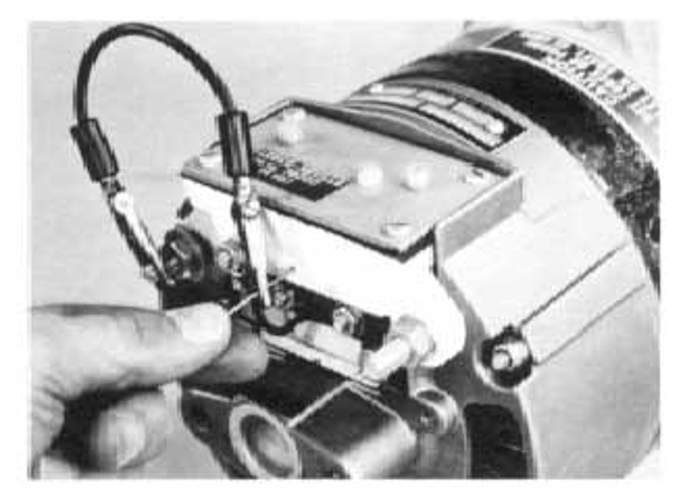
3. Connect the other end of the jumper to the negative (-) alternator output terminal and insert the wire in the FULL FIELD ACCESS HOLE (see photo). Hold the wire firmly against the brush terminal inside the housing. (Also flashes Field.)
4. With the jumper in place, connect a voltmeter across the alternator terminals and run the engine at approximately 1000 RPM. Compare this voltage reading with the voltage reading obtained in Step 1.
5. With the jumper still hooked up and the wire in the FULL FIELD ACCESS HOLE, connect an AC voltmeter across terminals 1&2, 1&3, and 2&3, and note the voltages. If all of the voltages are approximately the same, they are considered “balanced.”
6. Remove the jumper and wire from the alternator. If the voltage in Step 4 is higher than the voltage in Step 1, and the voltages measured in Step 5 are balanced, the stator and alternator are OK and you should proceed to the “Voltage Regulator Adjustment” procedure
If the voltage in Step 4 is higher than the voltage in Step 1, and the voltages measured in Step 5 are not balanced, the alternator stator or rectifier(s) defective. Repair or replace the alternator.
If the voltage in Step 4 is lower or equal to the voltage in Step 1, and the voltages measured in Step 5 are balanced, the alternator is defective. Replace alternator.
If the voltage in Step 4 is lower or equal to the voltage in Step1, and the voltages measured in Step 5 are not balanced, alternator stator or rectifier(s) are defective. Replace the alternator.
Voltage Regulator Adjustment
Leece-Neville alternators are equipped with one of two regulators. The Fully Adjustable Regulator has a flat cover plate. The Three-Step Regulator has a finned, curved cover plate. Use the following test procedure that is appropriate for your regulator type.
Fully Adjustable Regulator
NOTE: Battery must be at least 95% charged prior to this procedure. Also, make sure wire connections and belt tension are OK.
1. Shut off all electrical accessories and run the engine at approximately 1000 RPM.
2. Connect a voltmeter to the alternator outputs.
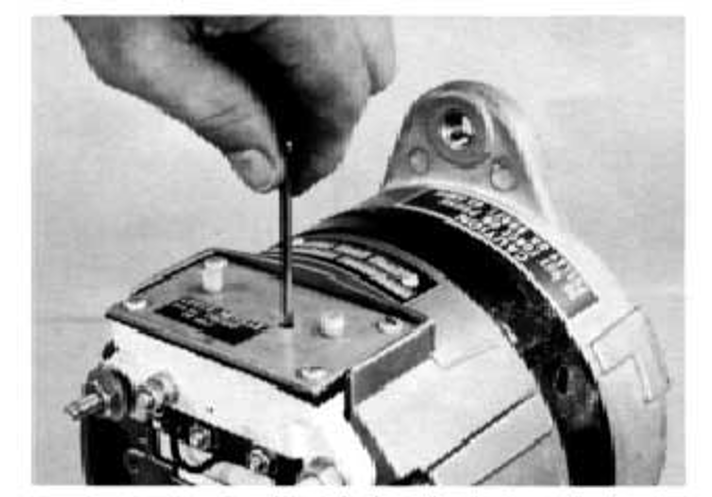
3. Remove the plastic screw from the regulator (see photo) and insert a small screwdriver in the hole. Engage the screwdriver blade in the slotted adjustment screw inside the regulator.
CAUTION: The adjustment potentiometer screw has high and low stops. DO NOT exert excessive pressure on the screwdriver or you may damage the regulator.
4. Turn the screwdriver clockwise to raise the voltage, counterclockwise to lower the voltage. Set the voltage between 14.0 and 14.2 volts (28.0 to 28.4 volts for 24-volt units).
CAUTION: DO NOT force the screwdriver past the set stops at either end of the adjustment range to avoid regulator damage.
5. Remove the screwdriver and voltmeter and install the plastic screw in the adjustment screw access hole.
Three-Step Adjustable Regulator
1. Stop the engine and disconnect the battery ground cable.
2. Remove the #10-32 nuts and lock washer from the regulator terminal and disconnect the diode trio lead (if the alternator is equipped with a diode trio).
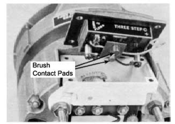
3. Remove the four screws from the regulator cover. Lift the regulator out of the housing and move it out of the way as far as the leads will permit. Inspect the two regulator brush contact pads (see photo). If dirt or corrosion is noted, clean the pads with #600 or finer sandpaper.
NOTE: In some cases, dirty or corroded contact pads can cause a low charge condition and voltage adjustment may not be necessary.
4. Inspect and reinstall the brushes.
5. To adjust the voltage, remove and reinstall the adjustment strap in one of three positions: between terminals A and B (low), between terminals A and C (medium), or between terminals B and C (high). Each change in the strap will result in an increase or decrease in the alternator output voltage of approximately 0.4 volts.