by Leese Neville
Source: Leece-Neville Heavy Duty Systems Division – Arcade, NY USA
Date: September 7, 2007
Bulletin No: TSB-1019
Models: All 12 Volt Alternators
Step 1: Visual Inspection. See Procedure 1.1. of TSB-1021
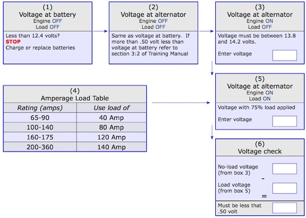
Step 2: Battery State of Charge: (Engine OFF) always remove the surface charge from batteries. To do this either, attach a carbon pile and load the batteries at 25% of the total CCA rating for 15 seconds or switch the headlamps on; select a high beam for 2 to 3 minutes per battery, then switch off headlamps. Allow the batteries to recover for 30 seconds, then test the battery’s true state of charge with a voltmeter. When a surface charge has been removed and battery voltage is found to be below 12.40 volts, charge or replace batteries before proceeding (see box 1 on page 2).
Step 3: Battery voltage verification at alternator terminals. Ensure that battery voltage is present when measured at the alternator positive (+) and negative (-) output terminals and between the negative (-) and “S” Remote Sense Terminal. This should be inspected with the engine off and all electrical accessories in the off position. This voltage should be the same as the battery voltage measured in the above step. If the voltmeter indication is .50 volt less than battery voltage, complete individual cable voltage drop test on the positive and negative cables. Correct voltage drop before proceeding. Refer to Prestolite training manual Section 3:2 below
Step 4: Alternator voltage test. Connect the test leads of a voltmeter to the alternator output terminals. Note:
Most Leece Neville alternators have isolated ground rectification. Always connect tester/voltmeter directly to the negative output terminal of the alternator or your test will be inaccurate.
• Start engine, increase to high idle (1500 RPM): The voltmeter should now indicate that the alternator output voltage has increased to a range from 13.8 volts to 14.2 volts. (Ensure that all electrical accessories of the vehicle are in the off position.) If voltage increases but is out of range, inspect to see if the alternator has an adjustable regulator. If so, reduce engine speed to idle and adjust voltage to a setting of 14.0 volts. If voltage is higher than 14.7 volts and cannot be adjusted below 14.25 volts, or if voltage is lower than 13.8 volts and cannot be adjusted into range then replace alternator.
• Inspect if voltage does not increase: If the alternator incorporates an ignition (IGN) terminal this terminal must have battery voltage present above 12.4 volts. If not; inspect the circuit for open and repair. If all is verified and alternator voltage has not increased or is out of range replace the alternator. If within range go to Step 5 (enter voltage into box 3 on page 2).
Step 5: Performance Test. Set engine speed to 1500 RPM.
• With either a carbon pile or with truck accessories apply a current load equal to 75% of rated output capacity of the alternator and maintain load for 5 to 10 seconds (see box 4 below). Test voltage after 10 seconds with a voltmeter at the alternator output terminals (enter voltage into box 5 below) If truck accessories are utilized for current loading this must be monitored with an inductive current device on the positive output cable of the alternator. (Note applying a load greater than 80% of rated output capacity of the alternator will cause the test to be inaccurate.)
• Properly functioning alternators will have a voltage drop of no more than .50 volts from no load to loaded states (see value from box 6 below). If the voltage drops more than .50 volts the alternator is considered to be defective.
3.2–The Primary Causes of Charging System Malfunction
Before discussing the preventive maintenance and diagnostic procedures for the charging system, were going to cover certain environmental and product application factors that can cause the charging system to malfunction.
Excessive heat. An alternator can become damaged if it operates too long at excessive temperatures. Damaging heat levels are generated in two ways: when the alternator becomes dirty either externally or internally restricting its ability to dissipate heat from its external surface or not allowing air to pass through the unit, and when air ducts and heat shields are not replaced after the alternator has been serviced.
Dirt and dust. Charging system components operate less efficiently when a buildup of dirt particles from around wire and cable connection points. Dirty connection points impair the flow of electrical current.
Vibration. If charging system components are poorly or loosely mounted to the vehicle’s frame, the resulting vibration can damage sensitive internal components. A loosely mounted component will also diminish the performance of the important belt drives. This is very important on high powered engines.