By Peter Martin
I recently replaced my Front and Rear TV with an LCD.
To upgrade the coach video components, the OEM Panasonic front, rear TV’s and VHS were replaced with Toshiba components. The following units were installed:
1. Toshiba – Progressive Scan DVD Player/VCR Combo with JPEG Playback, Model: SD-V296
2. 26AV502R 26″ Diagonal 720p HD LCD TV, Dimensions: 26.4 x 18.0 x 3.7
3. 19AV600U 18.5″ Diagonal 720p HD LCD TV, Dimensions: 18.74 x 12.72 x 2.53
4. The OEM satellite components are installed on the side cabinet above the driver’s seat, so this did not need to be touched.
The tools and supplies I used were a Makita compound miter saw, Craftsman 10” table saw, Kreg pocket screw jig and the usual screwdrivers, clamps, Red Oak of a nominal ¾’ thickness, finishing supplies, etc.
The first step in the process is to make sure you know what you
are up against. The Foretravel Yahoo Forum is an invaluable resource to
get you up to speed…I did. As the coach works in the Foretravel are
uniquely high quality, this actually makes the process easier and the final
product more professional looking as you can buy real wood (in my case red oak)
to fill-in or replace cabinet members as needed.
Back TV Removal & Installation:
The rear TV is removed by accessing the unit from the rear in the
1997 U270 WTBI layout. That means the bath closet has to be partially
dismantled. This involves partial removal of the clothes hanger rod and
an oak panel on the top portion of the closet side. Once removed, the
next step is to fabricate a mounting post for the TV flat panel mounting
bracket that fits the unit you decide to use (compound miter saw). The
mounting post incorporates the angles necessary to ensure the TV, when
installed, has the proper position for fit & viewing. The third try
was the charm as the compound angles are a bit difficult to reproduce.
Luckily the mounting post is made from inexpensive solid wood which I painted
flat black so as to mask the internal appearance of the finished unit.
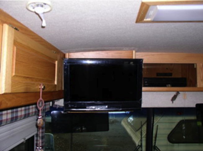
Front TV & VHS Removal:
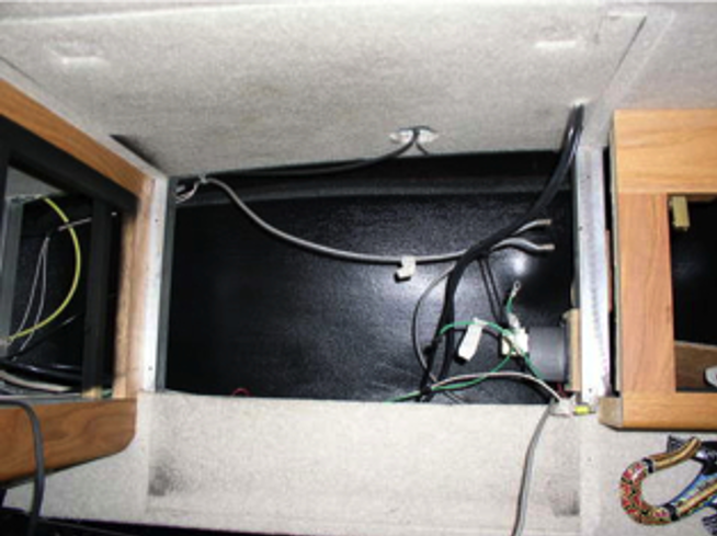
I first removed the VHS. This is not as easy as it sounds as the unit is installed prior to installing the front cabinet at the factory. The front cabinet doors were removed to make access to the work easier. Once the trim panels covering the VHS & Audiovox control center are removed, write down the cable routing from the VHS to the Audiovox. The Front TV removal involves removing the front Oak trim panel and the TV-securing pegs screwed to the ceiling panel. The legacy TV is heavy and a helper is nice so he/she can unscrew the coaxial cable, video cables and unplug the TV. Several screws hold the cabinet in place. Some are hidden and screw into the TV cabinet from the VHS cabinet. Depending on how the antenna booster wires are routed, these will have to be disconnected prior to the TV cabinet removal.
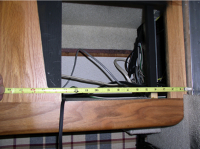
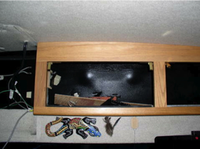
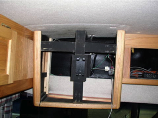
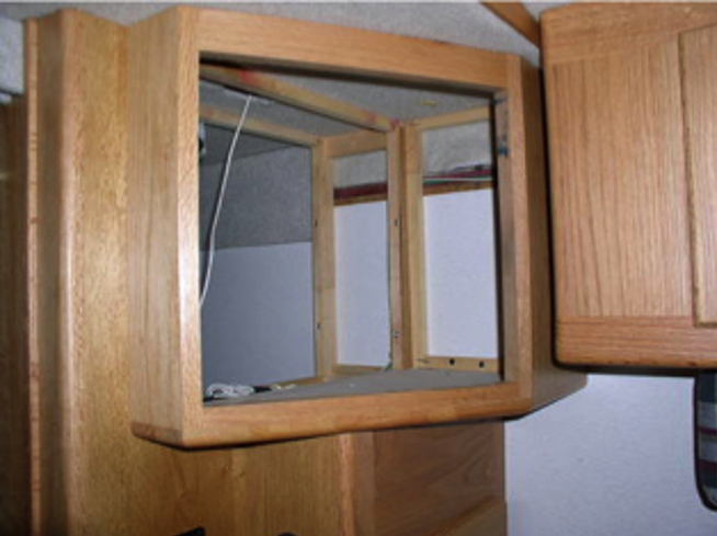
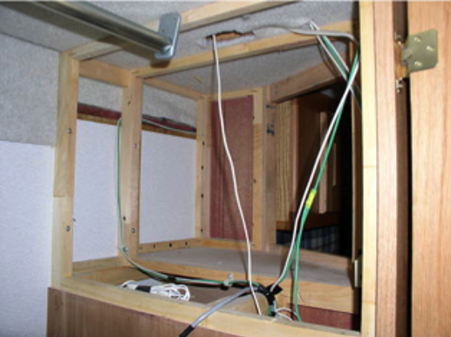
I wanted to reduce the depth of the cabinet by 5 inches so the final product would be as flush to the existing front cabinetry as possible. I cut off the 5-inch segment from the rear of the cabinet at the table saw. The rear and inside of the cabinet then have to be reconstructed as the original using 1 x 2 furring strips. Next, a mounting post for the flat panel mounting bracket has to be fabricated with the compound miter saw. I used ¾ inch red oak which I painted flat black to mask its visibility. The post is secured to the bottom supports of the front TV cabinet, the ceiling, and the structural aluminum frame. There are some tricky compound angles to deal with when fabricating the mounting post. Also, as I removed 5 inches from the TV cabinet depth, I had to strip the black paint from the factory, now visible on the street-side cabinet, as well as install a “filler” piece of 3/4’” Red Oak to hide the side cabinet opening, also now visible.
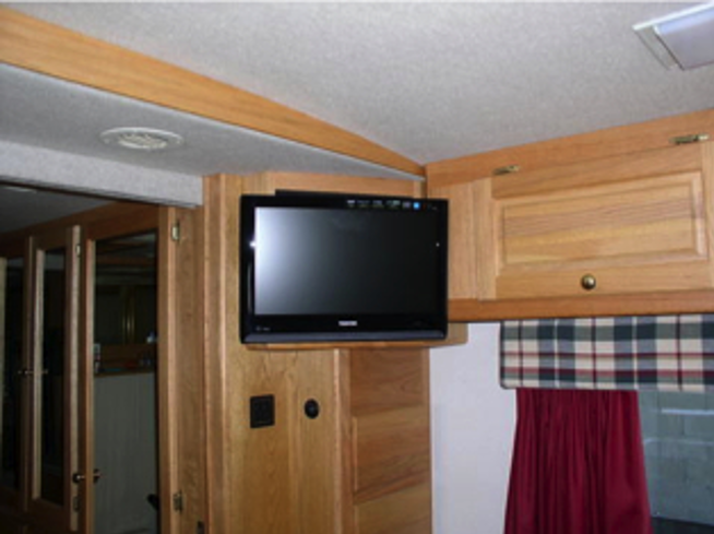
Front TV & VHS Reassembly:
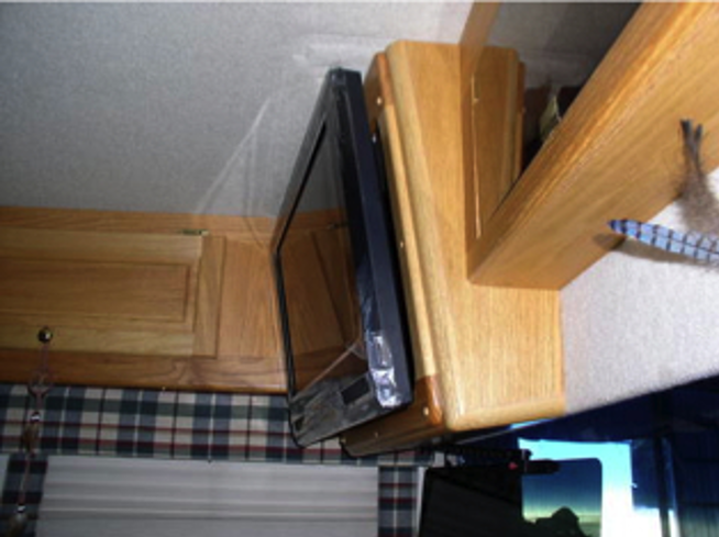
First, the TV cabinet is re-installed, the mounting post is installed to the cabinet, ceiling & aluminum structural coach frame. The antenna booster is reinstalled, and then the TV can be hung and secured in place. Next, the DVD/VHS combination unit is wired to the Audiovox VCC using an RF Modulator (Radio Shack purchase ~ $30) as this unit is not a recorder so there is no coax in/out available. This deficiency is corrected by plugging the RCA cables from the DVD/VHS to the RF Modulator and the coax from the RF modulator to the Audiovox VCC. The paneling is replaced as originally installed (quite difficult as the tolerances are tight), and you’re done!
I tested the performance of the components installed by first performing a test fit & wiring prior to the final trim installation. Also, I added a new spike protector (600 joules) while back there as the RF modulator needs 120v to operate.